Power device of dual-drive washing machine
A technology of a power unit and a washing machine is applied in the mechanical field to achieve the effects of simple and convenient switching, simple and convenient washing operation and drying operation
- Summary
- Abstract
- Description
- Claims
- Application Information
AI Technical Summary
Problems solved by technology
Method used
Image
Examples
Embodiment 1
[0035] figure 1 Shown is a schematic diagram of a direct drive motor for a dual-drive washing machine, combined below figure 1 Example 1 will be specifically described.
[0036] This embodiment includes a bracket 19, a stator 13 installed on the bracket 19, an outer rotor 9 installed on the outside of the stator 13, and an inner rotor 1 installed on the inside of the stator 13. When the electromagnetic winding of the stator 13 is energized, it will generate The direction of the magnetic field outside the stator 13 is opposite to the direction of the magnetic field inside the stator 13, resulting in the opposite direction of the electromagnetic force generated outside the stator 13 and inside the stator 13, so that the rotation of the outer rotor 9 and the inner rotor 1 is opposite. That is to say, the present embodiment uses a set of electromagnetic windings and a set of magnetic modulation rings to realize that the two rotors rotate in opposite directions, with little wear, ...
Embodiment 2
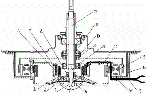
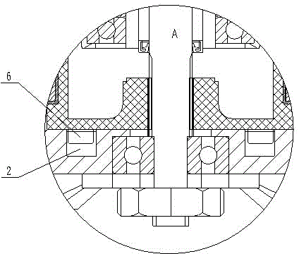
[0038] figure 2 Shown is a schematic diagram of the washing working conditions of Embodiment 2 of the dual-drive washing machine power unit, image 3 shown as figure 2 The enlarged schematic diagram of part A in middle, Figure 4 Shown is a schematic diagram of the spin-drying working condition of Embodiment 2 of the dual-drive washing machine power unit, Figure 5 shown as Figure 4 Enlarged schematic diagram of part B in middle.
[0039] Combine below figure 2 , image 3 , Figure 4 and Figure 5Specifically illustrate the power plant embodiment 2 of the dual-drive washing machine, which includes: a shell 14, a support 19 fixedly installed inside the shell 14, a direct drive motor mounted on the support 19, and the direct drive motor includes a fixed mount on the support 19. The stator 13, the inner rotor 1 installed inside the stator 13, and the outer rotor 9 installed outside the stator 13, the power unit of the double-drive washing machine also includes a dehyd...
Embodiment 3
[0051] Figure 6 Shown is a schematic diagram of the washing conditions of Embodiment 3 of the dual-drive washing machine power unit, Figure 7 shown as Figure 6 The partially enlarged schematic diagram of part C in the middle, Figure 8 Shown is a schematic diagram of the spin-drying working condition of Embodiment 3 of the dual-drive washing machine power unit, Figure 9 shown as Figure 8 Partial enlarged schematic diagram of part D in middle.
[0052] Combine below Figure 6 , Figure 7 , Figure 8 and Figure 9 Specifically illustrate the embodiment 3 of the double-drive washing machine power unit, which includes: a shell 14, a support 19 fixedly installed inside the shell 14, a direct drive motor installed on the support 19, and the direct drive motor includes a fixed drive on the support 19. Stator 13, the inner rotor 1 installed on the inner side of the stator 13, the outer rotor 9 installed on the outer side of the stator 13, this embodiment also includes a d...
PUM
 Abstract
Description
Claims
Application Information
 - R&D
- Intellectual Property
- Life Sciences
- Materials
- Tech Scout
- Unparalleled Data Quality
- Higher Quality Content
- 60% Fewer Hallucinations
Browse by: Latest US Patents, China's latest patents, Technical Efficacy Thesaurus, Application Domain, Technology Topic, Popular Technical Reports.
© 2025 PatSnap. All rights reserved.Legal|Privacy policy|Modern Slavery Act Transparency Statement|Sitemap|About US| Contact US: help@patsnap.com


