
Channel gate

A channel and gate technology, applied in the field of water conservancy gates, can solve problems such as inability to adjust, and achieve the effects of improving practicability, convenient use, and reasonable design

Inactive Publication Date: 2016-07-20
NORTH CHINA UNIV OF WATER RESOURCES & ELECTRIC POWER
View PDF7 Cites 6 Cited by
  • Summary
  • Abstract
  • Description
  • Claims
  • Application Information

AI Technical Summary

Problems solved by technology

[0002] At present, most of the existing gates are hydrostatic opening and closing structures. Although this structure can effectively meet the daily water storage and discharge requirements, the entire opening and closing process needs to be done manually, and cannot follow the upstream and downstream water levels. Real-time high and low self-adjustment

Method used


Image

  • Channel gate
  • Channel gate

Examples


Embodiment 1

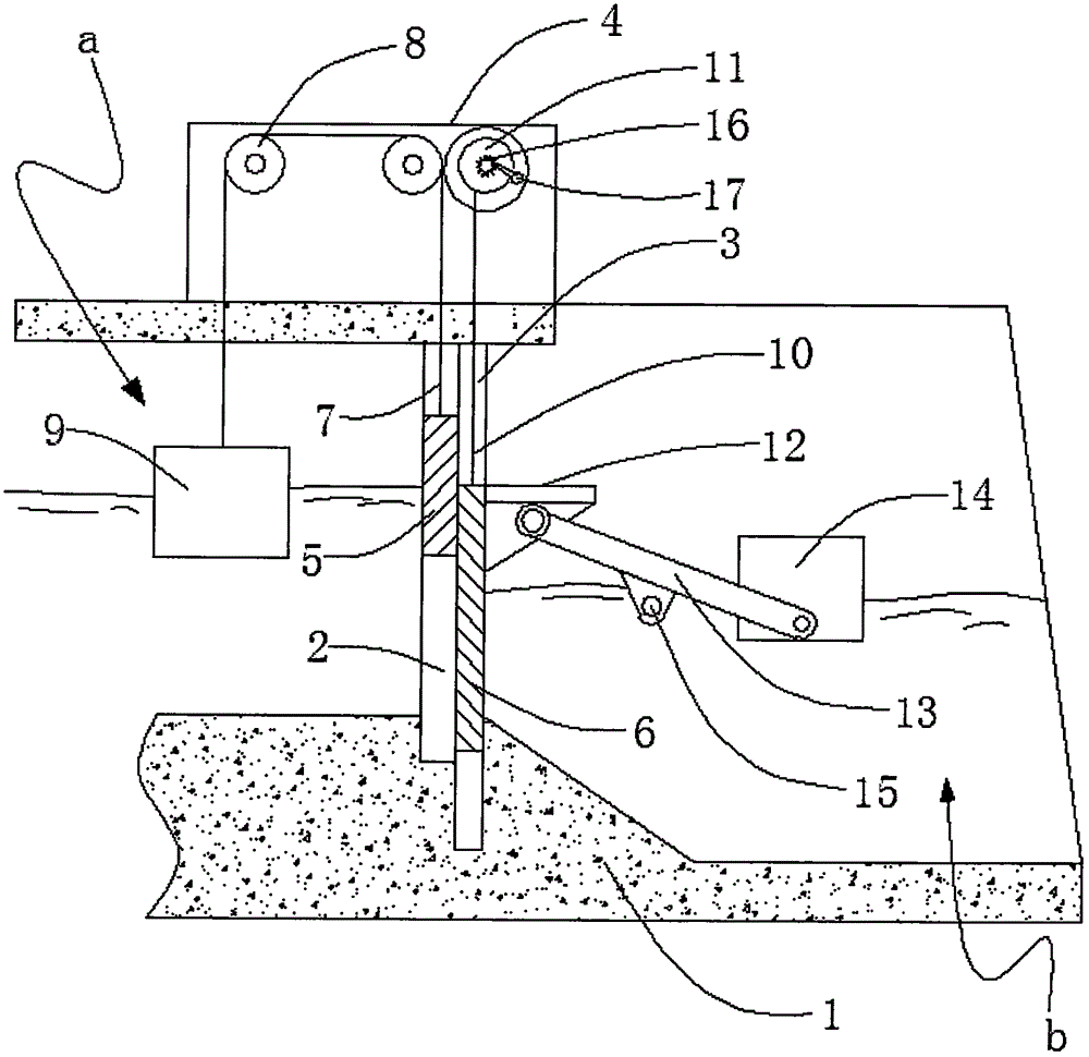
[0011] see Figure 1-2 , which includes a channel body 1, the channel body 1 is separated into an upstream water area a and a downstream water area b by a first groove 2 and a second groove 3, and a mounting plate 4 is arranged on the top of the channel body 1, so The first groove 2 described above is provided with a first gate 5 that is slidably matched with its clearance, and the second groove 3 is provided with a second gate 6 that is slidably matched with its clearance. The top of the first gate 5 is fixed with a first Steel wire rope 7, the other end of the first steel wire rope 7 is connected with the first buoy box 9 arranged in the upstream water area a through the pulley assembly 8 installed on the mounting plate 4, and the top of the second gate 6 is fixed with a second A steel wire rope 10, the other end of the second steel wire rope 10 is fixed on the steel cable reel 11, the steel cable reel 11 is installed on the mounting plate 4 through a rotating shaft, and a s...

Embodiment 2

[0013] When the upstream water level rose, the first pontoon 9 rose simultaneously, and the first gate 5 connected to the first pontoon 9 by the first wire rope 7 and the pulley assembly 8 sank by itself under its own weight. When the water level is gradually higher than the upper top edge of the first gate 5, the water flow will automatically flow to the downstream, that is to say, in this embodiment, the height control of the first gate 5 can be realized by controlling the length of the first steel wire rope 7, so that the upstream The water level is always kept at an appropriate level.

Embodiment 3

[0015] When the upstream is maintained at an appropriate water level and the downstream water level is low, the second buoyancy tank 14 descends by itself, and the entire second gate 6 is lifted by the connecting rod 13 and the bracket plate 12. Once the bottom of the second gate 6 is completely When crossing the lower bottom surface of the channel body 1, the upstream water body will pass through the bottom of the second gate 6 and be automatically replenished downstream.

[0016] Example 3

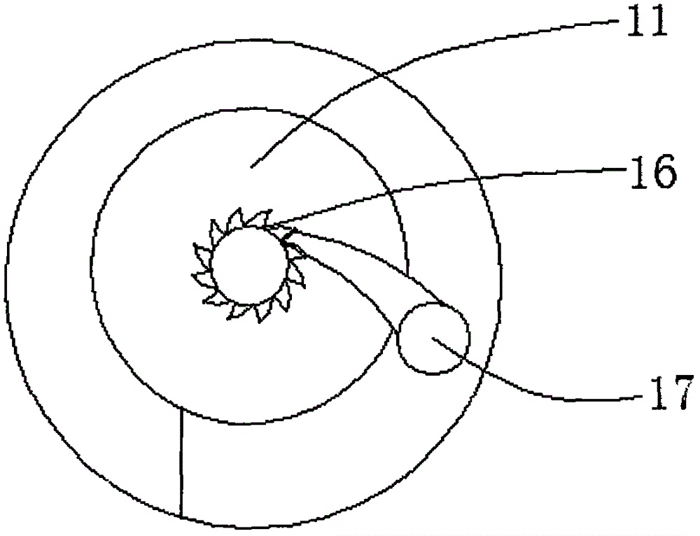
[0017] When the upstream and downstream water levels are kept at the preset positions but the upstream inventory needs to be cleared before the rainy season comes or the downstream is in the irrigation period, the motor is docked with the cable reel 11, and the ratchet 17 is shifted to engage with the ratchet 16 at the same time. Then start the motor, and the cable drum 11 gradually promotes the second gate 6 in the process of rotation. Once the bottom of the second gate 6 completely cro...


PUM


Abstract

The invention discloses a channel gate, which comprises a channel body (1); the inside of the channel body (1) is divided into an upstream water section a and a downstream water section b by a first groove (2) and a second groove (3); a mounting plate (4) is disposed on the top of the channel body (1); a first gate (5) is disposed in the first groove (2) by clearance sliding fit; a second gate (6) is disposed in the second groove (3) by clearance sliding fit; a first steel wire rope (7) is fixed on the top of the first gate (5); the other end of the first steel wire rope (7) is arranged to wind around a pulley block (8) mounted on the mounting plate (4), and then is connected with a first buoyancy tank (9) arranged in the upstream water section a. The channel gate disclosed by the invention achieves the advantages of simple structure, reasonable design and convenience in use, not only can the water level of the upstream and the downstream be adjusted automatically, but also the water level of the upstream and the downstream can be adjusted according to the actual situation effectively and automatically, and the channel gate has greatly improved practicability.

Description

technical field [0001] The invention relates to the technical field of water conservancy gates, in particular to a channel gate. Background technique [0002] At present, most of the existing gates are hydrostatic opening and closing structures. Although this structure can effectively meet the daily water storage and discharge requirements, the entire opening and closing process needs to be done manually, and cannot follow the upstream and downstream water levels. Real-time high and low self-adjustment. Contents of the invention [0003] The object of the present invention is to provide a channel gate, which can effectively solve the problems in the background technology. [0004] In order to solve the existing problems in the background technology, it includes a channel body 1, which separates the upstream water area a and the downstream water area b through the first groove 2 and the second groove 3 in the channel body 1. The top of the top is provided with a mounting ...

Claims


Application Information

Patent Timeline
Patent Type & Authority Applications(China)
IPC IPC(8): E02B7/26E02B7/36E02B7/50
CPCE02B7/205E02B7/26E02B7/36E02B7/50
Inventor 王声锋
Owner NORTH CHINA UNIV OF WATER RESOURCES & ELECTRIC POWER
Features
  • Generate Ideas
  • Intellectual Property
  • Life Sciences
  • Materials
  • Tech Scout
  • Unparalleled Data Quality
  • Higher Quality Content
  • 60% Fewer Hallucinations
Learn More