Blocking valve, grouting sleeve and prefabricated component connecting method

A grouting and sleeve technology, which is applied to building components, valve shell structures, lift valves, etc., can solve problems such as the inability to ensure the saturation of the cavity slurry, and the inability to evaluate the effect of sleeve grouting, so as to improve construction efficiency and strength. Effect

Pending Publication Date: 2016-07-20
BEIJING JIEYANTE ENG TECH
View PDF0 Cites 13 Cited by
  • Summary
  • Abstract
  • Description
  • Claims
  • Application Information

AI Technical Summary

Problems solved by technology

Since the sleeve body is an open space, the fluidity and self-tightness of the grout is used to fill the sleeve cavity during grouting connection. This method cannot guarantee the saturation of the grout inside the cavity. The existing detection method It is impossible to make a final judgment on the grouting effect in the sleeve, thus leaving engineering hidden dangers

Method used


Image

  • Blocking valve, grouting sleeve and prefabricated component connecting method
  • Blocking valve, grouting sleeve and prefabricated component connecting method
  • Blocking valve, grouting sleeve and prefabricated component connecting method

Examples


Embodiment 1

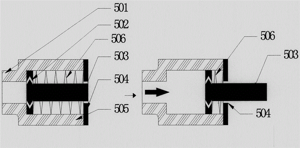
[0041] Example 1 see image 3 , image 3 Shown is the blocking valve 5 whose blocking body is a T-shaped blocking body 503 . The figure on the left shows the initial state of the check valve, the figure on the right shows the state of the check valve when it is filled with slurry, and the arrow at the connection end 501 in the figure on the right indicates the flow direction of the slurry. As shown in the figure, the blocking valve 5 in this embodiment includes a housing 505 , a T-shaped blocking body 503 , and a spring 506 . The casing 505 has a tubular cavity, one end of which extends outward to form a connection end 501 connected to the exhaust hole of the grouting sleeve, and the other end shrinks inward to the casing 505 to prevent the body from sliding out and the filling of the slurry in the tubular cavity can be observed. The limit observation port 504. The T-shaped blocking body 503 is located in the casing 505 between the connecting end 501 and the limit observati...

Embodiment 2

[0042] See Example 2 Figure 4 , Figure 4 Shown is the blocking valve 5 in which the blocking body is a spherical blocking body 507 . The figure on the left shows the initial state of the check valve 5, the figure on the right shows the check valve state when it is filled with slurry, and the arrow at the connection end 501 in the figure on the right indicates the flow direction of the slurry. Compared with the first embodiment, the main difference between this embodiment and the first embodiment is that the shape of the blocking body is different. Since the shape of the blocking body in this embodiment is spherical, it has good moving performance under the push of the slurry pressure. There is no connection between the body and the housing 505. Of course, in the specific implementation, this embodiment can also refer to the first embodiment to set a pressure scale.

Embodiment 3

[0043] See Example 3 Figure 5 , Figure 5 Shown is a blocking valve in which the blocking body is a sheet blocking body 508 . The figure on the left shows the initial state of the check valve, the figure on the right shows the state of the check valve when it is filled with slurry, and the arrow at the connection end 501 in the figure on the right indicates the flow direction of the slurry. The sheet-like blocking body 508 is connected with the inner wall of the casing 505 near the limit observation port 504 through the rotating shaft 509. The process is similar to the opening and closing process of the door. In the initial state, the sheet-like blocking body 508 is located in the cavity of the casing 505. , under the push of the slurry pressure, the sheet-like blocking body 508 rotates around the shaft 509. When the sheet-like blocking body 508 is completely rotated to the opening of the limit observation port 504 (eg Figure 5 Right), indicating that the grouting sleeve is ...


PUM


Abstract

The invention provides a blocking valve, a grouting sleeve and a prefabricated component connecting method. The steel bar connection grouting sleeve has a sealed space, and can be automatically sealed after grouting, and the grouting degree can be observed in a grouting process. Compared with an existing open sleeve, the grouting sleeve has the advantages that higher pressure can be born in the grouting process, the grouting sleeve can be automatically sealed after grouting, and the grout fullness of the sealed space can be observed in the grouting process, thereby monitoring the grouting quality of the grouting sleeve. The blocking valve, the grouting sleeve and the prefabricated component connecting method can be widely applied to a grouting sleeve connection process in the technical field of building construction.

Description

technical field [0001] The present application relates to the technical field of building construction, in particular to the connection of prefabricated components in the technical field of building construction. Background technique [0002] The prefabricated concrete structure system is the development direction of the industrialization upgrading of my country's civil engineering industry. Between prefabricated concrete components, the connection technology of steel bar joints is the key to ensure the construction quality of this technology. Reinforcement sleeve grouting connection technology is the first choice for prefabricated concrete reinforcement connection. [0003] Existing sleeve structures such as figure 1 As mentioned above, the sleeve body 1 is an open cylinder, and the grouting hole 2 and the exhaust hole 3 are formed on the cylinder body. When in use, the steel bars 4 are inserted into the cylinder from both ends of the sleeve body 1, and then pass through ...

Claims


Application Information

Patent Timeline
Patent Type & Authority Applications(China)
IPC IPC(8): E04C5/16F16K1/36F16K27/02
CPCE04C5/16F16K1/36F16K27/02
Inventor 徐建伟苗启松李文峰段世昌周博威周建孙瑜峰常政王海江
Owner BEIJING JIEYANTE ENG TECH
Why Eureka
Try Eureka