Slurry pocket slurry-injecting anchorage rod with control system and using method

A grouting bolt and control system technology, which is applied in the installation of bolts, earthwork drilling, mining equipment, etc., can solve the problem of lack of precise control of grouting amount and grouting pressure, complicated grouting engineering and low pullout resistance. and other problems, to achieve the effect of solving the excessive return pressure of the slurry, improving the quality of grouting, and enhancing the anti-pulling ability.

Pending Publication Date: 2018-06-01
NORTH CHINA INST OF SCI & TECH +1
View PDF9 Cites 3 Cited by
  • Summary
  • Abstract
  • Description
  • Claims
  • Application Information

AI Technical Summary

Problems solved by technology

[0002] At present, in the initial support of tunnels, bolt grouting is mostly used. After the arch and top grouting are completed, due to the pressure, the grout flows back, causing the bolts and grouting parts to be not densely grouted and have gaps, resulting in Excessive grouting pressure bursts the pipe and hurts people, and the grouting project is complicated, time-consuming and laborious; the grouting bag grouting anchor is widely recognized for its simple structure, convenient construction, and good effect. At present, coal mine roadway support and tunnel enclosure The common anchor bolts commonly used in the rock control process have low pull-out resistance, especially in water-rich and weak surrounding rock stability control projects. , and even lead to safety production accidents such as support failure, surrounding rock instability and collapse. The ordinary slurry bag grouting anchor technology was developed under this engineering background, but in the process of coal mine roadway support and tunnel surrounding rock control , because the grouting process mostly relies on the engineering experience of the operator, the amount of grouting and the grouting pressure lack precise control, there are common technical problems such as grouting and grouting, and even accidents involving pipe bursts and injuries due to excessive grouting pressure
[0003] The patent with application number CN201310166012.7 discloses a grouting anchor with a control valve, including a grouting control device, a grouting device, and a rod body device. The grouting control device includes a supporting shell, an adjustment unit, a limit unit, The grouting port and the grouting port can prevent the backflow of the grout, make the grouting dense, easy to operate, and avoid the explosion of the pipe due to excessive pressure during grouting, but the invention has no grout pocket, the rod body is fixed, and the control device can only be controlled by a mechanical Adjustment, operation is not flexible, can not meet the needs of different amounts of grouting, and can not achieve a good effect of preventing casualties caused by pipe burst due to excessive pressure of grouting

Method used


Image

  • Slurry pocket slurry-injecting anchorage rod with control system and using method
  • Slurry pocket slurry-injecting anchorage rod with control system and using method
  • Slurry pocket slurry-injecting anchorage rod with control system and using method

Examples


Embodiment 1

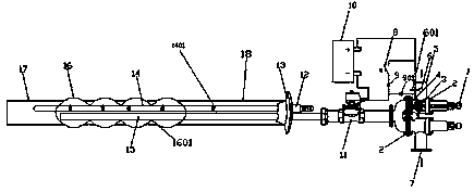
[0026] A grouting anchor with a control system, including a rod body part and a control part, and also includes a housing 18 outside the rod body part, and the control part includes a parallel grouting part, a grout return part and an activity above the grout return part In the connected control circuit part, the grouting part has a grouting port 7 with an opening downward, and the grouting part has a grouting port 5 with an upward opening, and there are flanges 2 on both sides of the grouting port 7 and the grouting port 5. There is a regulator 1 at the right end of the part and the return part, and the return part also includes an adjustment structure. The adjustment structure includes the regulator 1 and the spring 3 and the piston piece 4 between the flanges 2 at both ends of the return port 5, and one end of the spring 3 It is fixedly connected with the regulator 1, and the other end is fixedly connected with the piston piece 4, and the movement of the spring 3 is controll...

Embodiment 2

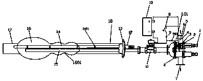
[0036] The difference between this embodiment and Embodiment 1 is that the main reinforcement is composed of five short main reinforcements. The slurry bag 16 is in the shape of two consecutive small beads and a large one. It is made of geotextile material. The retractable restraining band 1601 of the embodiment 1, the slurry bladder bag 16 of the present embodiment is stretched from the leftmost restraining band 1601 of Embodiment 1 into a large string of beads.

Embodiment 3

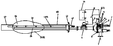
[0038] The difference between this embodiment and Embodiment 2 is that the pulp capsule bag 16 is in the shape of continuous beads, one small and one large, and is made of plastic film material. The restraint strap 1601 is elongated as a large bead.

[0039] The products of the three embodiments of embodiment 1, embodiment 2 and embodiment 3 are used for grouting, after testing, there is no situation that the grouting pressure is too large and accidents occur; The precise control of grouting pressure is obviously superior to that of ordinary grouting anchors, which solves the technical problems of excessive return pressure of ordinary grouting anchors, easy grout running, and grout leakage. It has simple structure, low cost, quick installation, and repeatability. It is suitable for the geological conditions of weak surrounding rocks such as coal mines and tunnels that need to be reinforced by grouting.


PUM


Abstract

The invention discloses a slurry pocket slurry-injecting anchorage rod with a control system and a using method and belongs to the technical fields of engineering construction and anchorage rod fixing. The slurry pocket slurry-injecting anchorage rod comprises a rod body part, a control part and a shell, the control part comprises a slurry injecting part and a slurry returning part which are connected in parallel and further comprises a control circuit part, and the slurry returning part comprises an adjusting structure. The control circuit part comprises a first bulb, a second bulb and a power source, a normally open switch is arranged above the first bulb, and the power source is connected with a normally open solenoid valve. The rod body part comprises a shell body, a main reinforcement, a slurry pocket and a pocket interior slurry-injecting pipe, a metal ball is arranged above a slurry returning opening, and the metal ball is connected with the normally open switch of the circuit part in parallel through an electric conducting metal bar. The slurry pocket slurry-injecting anchorage rod with the control system and the using method have the beneficial effects that the extraction-resisting capacity of the anchorage rod can be reinforced through control over the slurry-injecting shape, the slurry-injecting pressure can further be accurately controlled through the control system, and the technical problems that as for an ordinary slurry-injecting anchorage rod, the slurry backflow pressure is overlarge and slurry run-out and leaking are prone to occurring are solved; and theslurry pocket slurry-injecting anchorage rod has the advantages of being simple in structure, low in cost, rapid in mounting, capable of being reused and the like.

Description

technical field [0001] The invention discloses a grouting anchor with a control system and a use method thereof, belonging to the technical fields of engineering construction and anchor fixing. Background technique [0002] At present, in the initial support of tunnels, bolt grouting is mostly used. After the arch and top grouting are completed, due to the pressure, the grout flows back, causing the bolts and grouting parts to be not densely grouted and have gaps, resulting in Excessive grouting pressure bursts the pipe and hurts people, and the grouting project is complicated, time-consuming and laborious; the grouting bag grouting anchor is widely recognized for its simple structure, convenient construction, and good effect. At present, coal mine roadway support and tunnel enclosure The common anchor bolts commonly used in the rock control process have low pull-out resistance, especially in water-rich and weak surrounding rock stability control projects. , and even lead t...

Claims


Application Information

Patent Timeline
Patent Type & Authority Applications(China)
IPC IPC(8): E21D21/00E21D20/02
CPCE21D20/02E21D21/0026E21D21/0093
Inventor 赵启峰毕善军黄刚蔡祥雷黄仲文彭瑞刘本冲王安伟陈柳常奋斌范振权
Owner NORTH CHINA INST OF SCI & TECH
Why Eureka
Try Eureka