
Water source heat pump loop system

A water source heat pump and loop technology, which is applied in heat pumps, air conditioning systems, heating and ventilation control systems, etc., can solve the problems of resource waste, large power consumption, heat waste, etc., to avoid heat waste, avoid blockage, and save energy. Effect

Inactive Publication Date: 2016-07-20
WUXI OCEAN COOLING EQUIP YIZHENG
View PDF0 Cites 2 Cited by
  • Summary
  • Abstract
  • Description
  • Claims
  • Application Information

AI Technical Summary

Problems solved by technology

[0002] The use of cooling towers in factories is very common. Cooling towers can take out the heat released by the machine by means of circulating pipelines, and cool down the machine through circulating water to ensure the normal operation of the machine. However, many cooling towers bring out The heat can not be well utilized, which leads to waste of heat and waste of resources. Many enterprises use air conditioners to adjust the temperature. Generally, air conditioners rely on electricity as the driving force for temperature control. It needs to consume a lot of electricity, which brings a burden to the operating cost of the enterprise. Some enterprises transfer the heat from the cooling tower to the air conditioner, so that the operation of the air conditioner can be powered by the cooling tower, which saves the operating cost of the enterprise and can also transfer the heat Use it to protect the surrounding environment

Method used


Image

  • Water source heat pump loop system

Examples


Embodiment Construction

[0010] The present invention will be further described below in conjunction with the accompanying drawings.

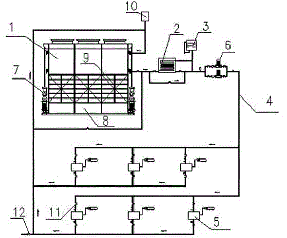
[0011] A water source heat pump loop system is provided with a cooling tower 1, a heating device 2 and a circulating water tank 3, the heating device 2 is connected next to the cooling tower 1, the heating device 2 and the circulating water tank 3 are connected to each other, and a circulating pipe is arranged around the cooling tower 1 Road 4, the circulation pipeline 4 is connected with the air-conditioning main engine 5, the water pump 6 is arranged behind the circulating water tank 3, a thermometer is arranged between the circulating water tank 3 and the water pump 6, and a control valve is arranged on both sides of the heating device 2, and the control valve is a ball valve. There is a circulation circuit under the device 2, and a control valve is provided on the circulation circuit. There are descaling parts 7 on both sides of the cooling tower 1. The descaling pa...


PUM


Abstract

Disclosed is a water source heat pump loop system. A cooling tower, a heating device and a circulating water tank are arranged. The heating device is connected to the side of the cooling tower, and the heating device and the circulating water tank are connected with each other. A circulating pipeline is arranged around the cooling tower, and an air conditioner host is connected to the circulating pipeline. A water pump is arranged behind the circulating water tank, and a thermometer is arranged between the circulating water tank and the water pump. Control valves are arranged on the two sides of the heating device, and ball valves serve as the control valves. A circulating loop is arranged on the lower portion of the heating device, and a control valve is arranged on the circulating loop. Due to the fact that the cooling tower and an air conditioner are connected with each other through the circulating pipeline, the heat can be transferred to the air conditioner through the pipeline, energy is saved, the waste of the heat of the cooling tower is avoided, the effect of waste utilization is achieved, and the phenomenon that a large amount of heat is released in vain is avoided. Due to the fact that descaling components are arranged on the two sides of the cooling tower, water scale in the cooling tower can be timely cleaned away, accumulation of water scale in the cooling tower is prevented, and the phenomenon that the cooling tower is blocked by water scale is avoided.

Description

technical field [0001] The invention relates to a heat pump circulation system, in particular to a water source heat pump circulation system. Background technique [0002] The use of cooling towers in factories is very common. Cooling towers can take out the heat released by the machine by means of circulating pipelines, and cool down the machine through circulating water to ensure the normal operation of the machine. However, many cooling towers bring out The heat can not be well utilized, which leads to waste of heat and waste of resources. Many enterprises use air conditioners to adjust the temperature. Generally, air conditioners rely on electricity as the driving force for temperature control. It needs to consume a lot of electricity, which brings a burden to the operating cost of the enterprise. Some enterprises transfer the heat from the cooling tower to the air conditioner, so that the operation of the air conditioner can be powered by the cooling tower, which saves ...

Claims


Application Information

Patent Timeline
Patent Type & Authority Applications(China)
IPC IPC(8): F25B30/06F28G9/00F24F5/00F24F11/02
Inventor 杨波
Owner WUXI OCEAN COOLING EQUIP YIZHENG
Learn More