Current control circuit and electrode water level monitoring device

A technology of current control circuit and control circuit, which is applied in the direction of measuring device, lubrication indicator device, liquid/fluid solid measurement, etc. It can solve the problems of reducing the accuracy of liquid level monitoring, the electrode can not conduct electricity, and the electrode is oxidized and rusted, so as to improve the The effect of monitoring accuracy, ensuring electrical conductivity, and reducing misjudgment of liquid level

Active Publication Date: 2016-07-20
CHINA ELECTRONICS PROD RELIABILITY & ENVIRONMENTAL TESTING RES INST
View PDF9 Cites 2 Cited by
  • Summary
  • Abstract
  • Description
  • Claims
  • Application Information

AI Technical Summary

Problems solved by technology

[0004] But when it is actually used, this switch has a disadvantage. Applying AC voltage to the two electrodes for a long time will easily cause the electrodes to oxidize and rust or absorb a large amount of impurities in the liquid, resulting in the electrodes being unable to conduct electricity, or the conduction signal is intermittent. Occurs, reducing the accuracy of liquid level monitoring

Method used


Image

  • Current control circuit and electrode water level monitoring device
  • Current control circuit and electrode water level monitoring device

Examples


Embodiment Construction

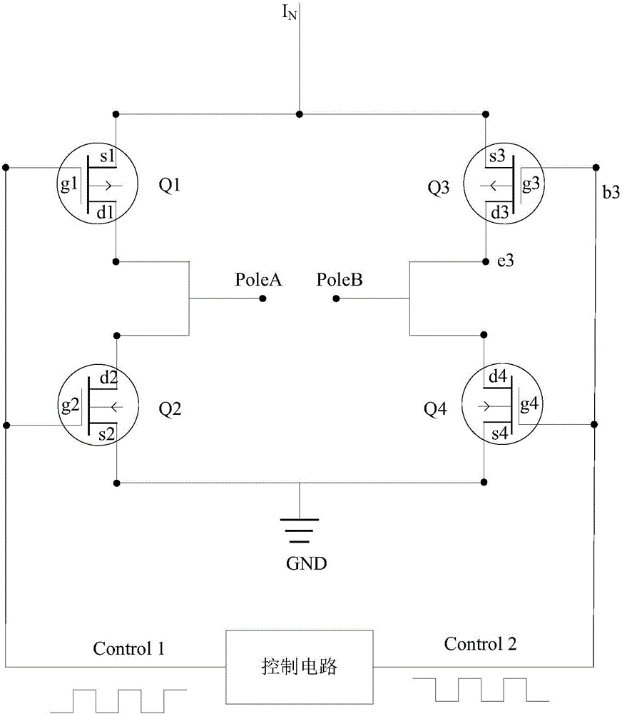
[0016] refer to figure 1 as shown, figure 1 It is a structural schematic diagram of a current control circuit, including: transistors Q1, Q2, Q3 and Q4, and a control circuit;

[0017] The control circuit outputs the first pulse signal Control1 and the second pulse signal Control2 with opposite waveforms in a set cycle;

[0018] The sources s1 and s2 of the triodes Q1 and Q3 are connected and connected to the working current I N ;

[0019] The gates g1 and g2 of the triodes Q1 and Q2 are connected and connected to the first pulse signal Control1; the gates g3 and g4 of the triodes Q3 and Q4 are connected and connected to the second pulse signal Control2;

[0020] The drain d1 of the triode Q1 is connected to the drain d2 of Q2 and connected to the first electrode PoleA; the drain d3 of the triode Q3 is connected to the drain d4 of Q4 and connected to the second electrode PoleB;

[0021] The source s2 of the triode Q2 is connected to the source s4 of Q4 and connected to the...


PUM


Abstract

The invention relates to a current control circuit and an electrode water level monitoring device. The current control circuit comprises a triode Q1, a triode Q2, a triode Q3, a triode Q4 and a control circuit. The control circuit outputs a first pulse signal and a second pulse signal opposite in waveform according to the set period. A source electrode s1 of the triode Q1 and a source electrode s2 of the triode Q3 are connected, and work currents are introduced. A grid electrode g1 of the triode Q1 and a grid electrode g2 of the triode Q2 are connected, and the first pulse signal is introduced. A grid electrode g3 of the triode Q3 and a grid electrode g4 of the triode Q4 are connected, and the second pulse signal is introduced. A drain electrode d1 of the triode Q1 and a drain electrode d2 of the triode Q2 are connected, and are connected with a first electrode. A drain electrode d3 of the triode Q3 and a drain electrode d4 of the triode Q4 are connected and are connected with a second electrode. A source electrode s2 of the triode Q2 and a source electrode s4 of the triode Q4 are connected and grounded. According to the technology, electrode oxidizing and rusting or liquid impurity adsorbing caused by long-time alternating-current voltages is avoided, the conductive performance of the electrodes is ensured, wrong judgment on the liquid level is reduced, and the monitoring accuracy is improved.

Description

technical field [0001] The invention relates to the technical field of electrode water level monitoring, in particular to a current control circuit and an electrode water level monitoring device. Background technique [0002] The water level switch is a switch used to control the liquid level. It is mainly divided into contact type and non-contact type in form. Among them, the contact float type liquid level switch is the most widely used. In many industrial production processes, water level switches are often used to judge liquid state, measure liquid height, volume, etc. For example, in recent years, with the shortage of water resources and the improvement of market requirements for energy saving and environmental protection performance of home appliances, for example, In Europe and North America, the water-saving indicators for home appliances have entered the legislative process, and good water-saving performance has become an important technical development trend of th...

Claims


Application Information

Patent Timeline
Patent Type & Authority Applications(China)
IPC IPC(8): G01F23/00
CPCG01F23/00
Inventor 郑建福邓海兵徐伟权罗亦坤马军
Owner CHINA ELECTRONICS PROD RELIABILITY & ENVIRONMENTAL TESTING RES INST
Why Eureka
Try Eureka