Experimental platform for material mechanics

An experimental platform and technology of material mechanics, applied in the field of material mechanics experimental platform, can solve the problems of complex operation and inconvenient handling of equipment, and achieve the effect of convenient transfer, easy handling and simple structure

Inactive Publication Date: 2016-07-20
YANCHENG INST OF TECH
6 Cites 2 Cited by

AI-Extracted Technical Summary

Problems solved by technology

[0003] The purpose of the present invention is to provide a material mechanics experiment platform, which solv...

Abstract

The invention discloses an experimental platform for material mechanics.The experimental platform comprises a frame, the bottom of the frame is provided with moving devices, and the middle of the frame is provided with a tensile experiment device; the tensile experiment device comprises a first chuck, a second chuck and an air cylinder, the first chuck and the air cylinder are arranged on the inner side of the frame, the second chuck is installed at the end of the air cylinder, and the second chuck corresponds to the first chuck; each moving device comprises a support frame and a rolling wheel, wherein the support frame is installed below the frame, and a first rotating shaft is arranged in the support frame in a penetrating mode and provided with the rolling wheel.The experimental platform is simple in structure and convenient to carry.

Application Domain

Educational modelsStrength properties

Technology Topic

EngineeringTensile testing

Image

  • Experimental platform for material mechanics
  • Experimental platform for material mechanics

Examples

  • Experimental program(1)

Example Embodiment

[0021] The principles and features of the present invention will be described below with reference to the accompanying drawings. The examples cited are only used to explain the present invention, not to limit the scope of the present invention.
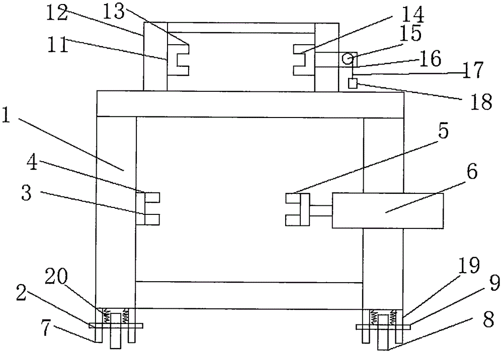
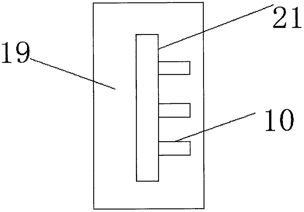
[0022] Such as figure 1 As shown, the embodiment of the present invention provides a material mechanics experiment platform, which includes a frame 1, a moving device 2 is provided at the bottom of the frame 1, and a tensile test device 3 is provided in the middle of the frame 1, the tensile test device 3 It includes a first chuck 4, a second chuck 5, and a cylinder 6. The first chuck 4 and the cylinder 6 are respectively arranged inside the frame 1, and the second chuck 5 is installed at the end of the cylinder 6, and The second chuck 5 corresponds to the first chuck 4. The moving device 2 includes a support frame 7 and a roller 8. The support frame 7 is installed below the frame 1, and the support frame 7 is provided with a first rotating shaft 9 therethrough, A roller 8 is provided on the first rotating shaft 9.
[0023] A torsion test device 11 is provided above the frame 1. The torsion test device 11 includes a bracket 12, a first torsion clamp base 13, a second torsion clamp base 14, a support rod 15 and a second rotating shaft 16, and the bracket 12 is installed Above the frame 1 and on both sides of the bracket 12 are respectively installed a first torsion clamp base 13 and a second torsion clamp base 14, the second rotating shaft 16 is installed at the end of the second torsion clamp base 14, and the end of the second rotating shaft 16 A support rod 15 is provided on the support rod 15, a steel wire 17 is wound around the support rod 15, and a weight 18 is provided at the end of the steel wire 17.
[0024] The spring is formed by bushing an inner spring and an outer spring, the outer spring is sleeved outside the inner spring, and the inner wall of the upper and lower ends of the outer spring is welded with the outer walls of the upper and lower ends of the inner spring.
[0025] When in use, you can know the torsion force by the number of weights 18, which is convenient for experiment;
[0026] Wherein, the support frame 7 includes two baffles 19, the baffles 19 are arranged at intervals, the roller 8 is located between the baffles 19, and it also includes a spring 20, one end of the spring 20 is connected to the bottom of the frame 1, The other end is connected to the first rotating shaft 9, the baffle 19 is provided with a longitudinal sliding groove 21, the outer side of the sliding groove 21 is evenly provided with a transverse clamping groove 10, and the first rotating shaft 9 is arranged in the sliding groove 21 ;
[0027] When in use, if it needs to be transported, the first rotating shaft 9 is moved in the sliding groove 21 to ensure that the roller 8 is exposed and convenient to move; in the experiment, the first rotating shaft 9 is moved in the sliding groove 21 to ensure that the roller 8 can Retract the baffle 19 to ensure stability.
[0028] The above are only the preferred embodiments of the present invention. It should be pointed out that for those of ordinary skill in the art, without departing from the principle of the present invention, several improvements and modifications can be made, and these improvements and modifications should also be made. It is regarded as the protection scope of the present invention.

PUM

no PUM

Description & Claims & Application Information

We can also present the details of the Description, Claims and Application information to help users get a comprehensive understanding of the technical details of the patent, such as background art, summary of invention, brief description of drawings, description of embodiments, and other original content. On the other hand, users can also determine the specific scope of protection of the technology through the list of claims; as well as understand the changes in the life cycle of the technology with the presentation of the patent timeline. Login to view more.

Similar technology patents

Photoelectric sensor for position of sun

InactiveCN101650173AEffective tracking range expandedSimple structure
Owner:WUHAN UNIV OF TECH

Magnetic cooling apparatus and control method thereof

ActiveUS20130180263A1simple structure
Owner:SAMSUNG ELECTRONICS CO LTD

Dual-Drivetrain of Power-Assist Vehicle

InactiveUS20100181130A1enhance uphill momentumsimple structure
Owner:CHOU WEN CHENG

Classification and recommendation of technical efficacy words

  • Simple structure
  • easy to operate

Lancet device

InactiveUS7303573B2inexpensively mass-producedeasy to operate
Owner:ABBOTT DIABETES CARE INC

Rapid and non-invasive optical detection of internal bleeding

InactiveUS20050065436A1easy to operaterapid and accurate result
Owner:HO WINSTON ZONH +2
Why Eureka
Try Eureka