
Microprobe with rake-shaped cantilever structure and preparation method thereof

A technology of cantilever beams and microprobes, applied in the direction of microstructure technology, microstructure devices, microstructure devices composed of deformable elements, etc., can solve the problems of poor accuracy and repeatability, and achieve improved stability Effect

Active Publication Date: 2016-07-20
颍上县祥盛建设管理有限公司
View PDF11 Cites 1 Cited by
  • Summary
  • Abstract
  • Description
  • Claims
  • Application Information

AI Technical Summary

Problems solved by technology

[0009] The purpose of the present invention is to provide a microprobe with a rake-shaped cantilever beam structure to solve the problem of poor accuracy and repeatability of the traditional microprobe cantilever beam due to shaking / vibration

Method used


Image

  • Microprobe with rake-shaped cantilever structure and preparation method thereof
  • Microprobe with rake-shaped cantilever structure and preparation method thereof
  • Microprobe with rake-shaped cantilever structure and preparation method thereof

Examples


Embodiment Construction

[0033] It should be noted that, in the case of no conflict, the embodiments in the present application and the features in the embodiments can be combined with each other. The present invention will be described in detail below with reference to the accompanying drawings and examples.

[0034] It can be understood that the essence of the microprobe (CN104931741A) disclosed in the prior art is to finely control the vibration of the cantilever beam in the measurement direction, while the vibration control of the cantilever beam in other directions is not considered. The invention utilizes the connection structure to fix the cantilever beams of the microprobes, suppresses the lateral displacement (vibration and drift) between the cantilever beams during the measurement process, and eliminates the system error introduced by the position change during the probe method measurement process.

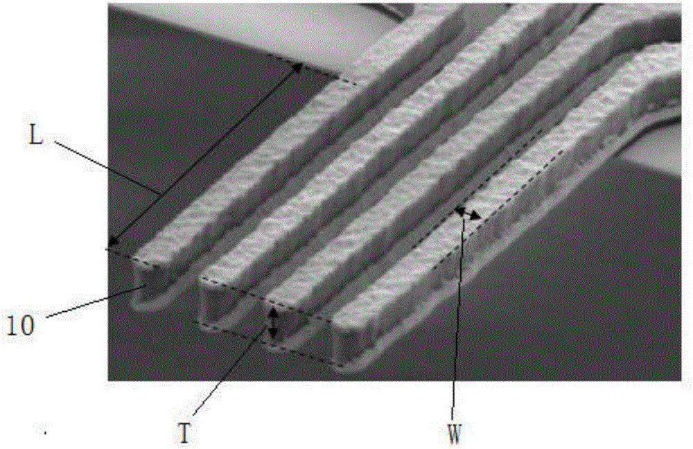
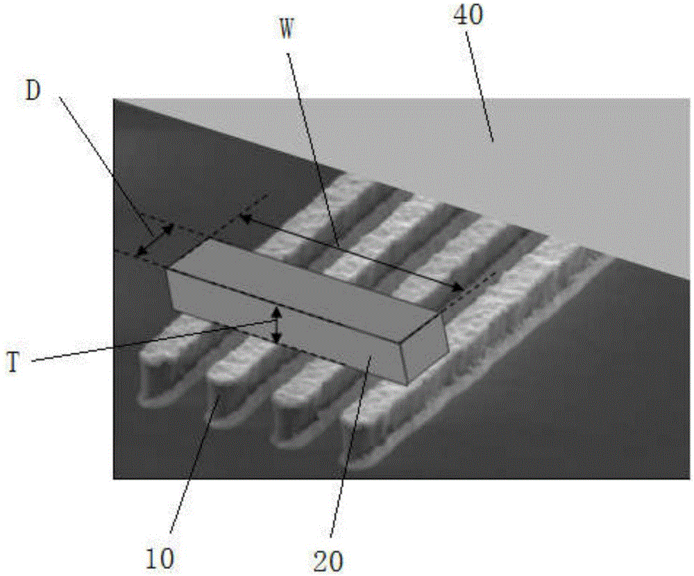
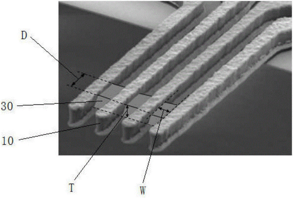
[0035] figure 1 is an enlarged view of the structure of the microprobe. The microprobe inc...


PUM

PropertyMeasurementUnit
Thicknessaaaaaaaaaa
Depthaaaaaaaaaa
Widthaaaaaaaaaa

Abstract

The present invention discloses a microprobe with rake-shaped cantilever structure and a preparation method thereof. The microprobe comprises a set of cantilever beams and a connection structure reserved or additionally installed at the end of the set of the cantilever beams in the process of the microprobe, and the connection structure is configured to restrain side-way movement of the end of the cantilever beams. The microprobe is able to restrain the sideway jittering / vibration of each cantilever beam through a connection structure to effectively realize the jittering / vibration control of the cantilever beams and overcome the problem of unstable measurement result.

Description

technical field [0001] The invention relates to a microprobe with a rake-shaped cantilever beam structure and a preparation method thereof. Background technique [0002] With the innovation of material science detection technology and the requirements of process control, microprobes are used as a means of electrical measurement in the application of 4-probe measurement (4pp), current coplanar tunneling measurement (CIPT), and voltage / current curve relationship. The field is facing more stringent requirements. [0003] During the measurement, each cantilever is in contact with the sample, some stress is applied to make electrical contact, and each cantilever can pass a current to obtain the potential at that point. [0004] C.LPetersen et al. disclosed a structure, preparation method and testing method of a microprobe in the European patent document EP1085327A1 whose invention name is "Multi-pointprobe". D.CWorledge et al. Patent document US6927569B2 discloses a microprobe ...

Claims


Application Information

Patent Timeline
IPC IPC(8): G01R1/067B81B3/00
CPCB81B3/007G01R1/06727
Inventor 朱干军
Owner 颍上县祥盛建设管理有限公司
Learn More