GNSS signal simulator time delay calibration system and GNSS signal simulator time delay calibration method

A technology for calibrating systems and simulators, which is applied in satellite radio beacon positioning systems, radio wave measurement systems, instruments, etc., and can solve the problems of unguaranteed delay consistency of simulators, inability to guarantee standardization of calibration operations, subjective reading errors, etc. question

Active Publication Date: 2016-07-20
BEIJING INST OF RADIO METROLOGY & MEASUREMENT
View PDF4 Cites 11 Cited by
  • Summary
  • Abstract
  • Description
  • Claims
  • Application Information

AI Technical Summary

Problems solved by technology

However, in the test of various indicators of the receiver, especially the test and calibration of the receiver delay, the output of the simulator is not a special signal simulation scene with a pseudo-range of zero, but a normal signal simulation scene with a pseudo-range that changes with time. In this scenario, the consistency of the delay of the simulator cannot be guaranteed; in addition, the method of observing and judging the delay between the rising edge of the second pulse and the initial code phase of the pseudo-code through a high-speed oscilloscope will also introduce subjective reading errors, which cannot guarantee the standardization of calibration operations

Method used


Image

  • GNSS signal simulator time delay calibration system and GNSS signal simulator time delay calibration method
  • GNSS signal simulator time delay calibration system and GNSS signal simulator time delay calibration method
  • GNSS signal simulator time delay calibration system and GNSS signal simulator time delay calibration method

Examples


Embodiment Construction

[0046] In order to illustrate the present invention more clearly, the present invention will be further described below in conjunction with preferred embodiments and accompanying drawings. Similar parts in the figures are denoted by the same reference numerals. Those skilled in the art should understand that the content specifically described below is illustrative rather than restrictive, and should not limit the protection scope of the present invention.

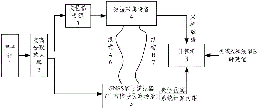
[0047] like figure 1 As shown, the present invention discloses a system for time delay calibration of GNSS signal simulator, which system includes atomic clock 1, isolation distribution amplifier 2, vector signal source 3, data acquisition equipment 4, satellite navigation signal simulator 5, line Cable A6, cable B7 and computer 8.

[0048]The atomic clock 1 provides an external clock signal for the system, and the isolation distribution amplifier 2 divides the external clock signal into a first clock signal and a second ...


PUM


Abstract

The invention discloses a GNSS signal simulator time delay calibration system and a GNSS signal simulator time delay calibration method. The GNSS signal simulator time delay calibration system comprises an isolation amplifier, a satellite navigation signal simulator, a data acquisition module, and a signal processing module. The isolation amplifier is used to divide an external clock signal into a first clock signal and a second clock signal. The satellite navigation signal simulator adopts the first clock signal as the working clock, and is used to output a radio frequency navigation signal and a second pulse signal in a normal simulation scene that the receiving device is in the static state, and the simulator pseudo-range is time-varying. The data acquisition module adopts the second clock signal as the sampling clock, and is used to acquire the radio frequency navigation signal and the second pulse signal. The signal processing module is used to calculate the pseudo-range corresponding to the radio frequency navigation signal and the pseudo-range recorded by the simulation epoch moment simulator disposed on the rising edge of the second pulse signal based on the acquired radio frequency navigation signal and the acquired second pulse signal, and then the own time delay of the satellite navigation signal simulator can be acquired. By adopting the technical scheme, the special scene of the zero pseudo-range or the fixed pseudo-range is not required, and the calibration of the simulator time delay can be realized under the condition of the simulator normal simulation scene signal output.

Description

technical field [0001] The invention relates to a time delay calibration method. More specifically, it relates to a system and method for delay calibration of a GNSS signal simulator. Background technique [0002] Global Navigation Satellite System (GNSS, Global Navigation Satellite System) is an all-weather radio navigation system established by using navigation satellites. It has been widely used in the fields of surveying and mapping remote sensing, timing, navigation and positioning. The GNSS signal simulator (hereinafter referred to as the simulator) is a high-precision standard signal source, which can simulate and generate navigation signals transmitted by navigation satellites in the actual environment and reach the navigation receiver through space propagation, and provide signal simulation scenarios for the receiver. Key test equipment in receiver R&D design. By simulating different signal simulation scenarios, the simulator can test and verify different performa...

Claims


Application Information

Patent Timeline
Patent Type & Authority Applications(China)
IPC IPC(8): G01S19/23
Inventor 李世光焦月张明杨军王伟
Owner BEIJING INST OF RADIO METROLOGY & MEASUREMENT
Why Eureka
Try Eureka