Snow depth measurement system based on covering detection

A technology for measuring systems and coverings, applied to measuring devices, rainfall/precipitation gauges, instruments, etc., can solve problems such as measurement errors, large influence of temperature and wind speed, and difficult accurate measurement of snow rulers, so as to reduce the number of false alarms and improve The effect of accuracy

Inactive Publication Date: 2016-07-20
BEIJING JIAOTONG UNIV
View PDF10 Cites 4 Cited by
  • Summary
  • Abstract
  • Description
  • Claims
  • Application Information

AI Technical Summary

Problems solved by technology

[0003] The traditional method is to use a snow measuring stick or a graduated snow measuring rod to be inserted into the snow to the ground surface to measure the snow depth on the ground. Because there is usually an ice layer under the snow, it is difficult to measure accurately with the snow measuring stick, and at the same time, the snow caused by wind blowing Snow is redistributed, so representative measurement points and multiple measurements need to be selected, this method is time-consuming and laborious, has large random errors, and is difficult to monitor in real time
[0004] At present, the existing snow depth measurement methods include radioisotope method, which has high accuracy but will endanger the health of surveyors; the measurement method based on image processing is greatly affected by weather and light, and its robustness is poor; the ultrasonic sensor snow depth measurement method, its It is greatly affected by temperature and wind speed, and the snow depth measurement method based on the phase method laser ranging principle has strong stability but is affected by the unevenness of the snow surface
Existing snow depth monitoring devices for high-speed railways are mainly based on the laser ranging method to measure snow depth. This measurement method requires that no obstructions are allowed on the laser measurement path, otherwise it will cause measurement errors
However, in the actual application environment of high-speed railway, it is inevitable that other objects enter the measurement area and block the snow depth measurement

Method used


Image

  • Snow depth measurement system based on covering detection

Examples


Embodiment Construction

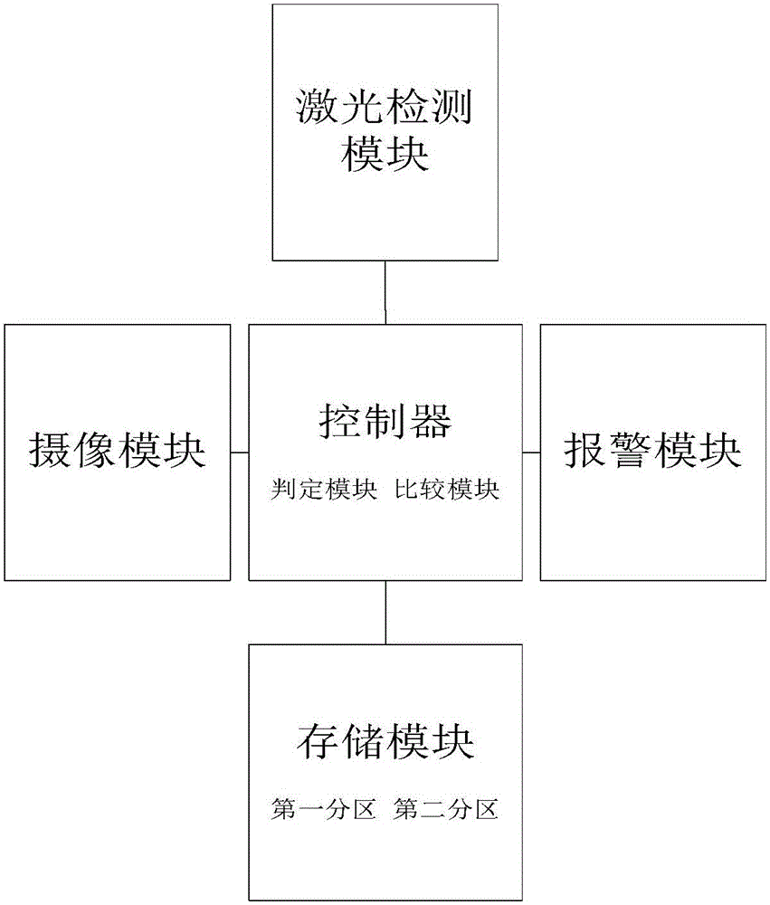
[0015] Such as figure 1 As shown, the snow depth measurement system of the present invention includes a laser detection module, a storage module, a camera module, a controller, and an alarm module.

[0016] The laser detection module is used to detect the snow depth value of the area to be measured in real time;

[0017] a storage module, configured to store the snow depth value measured by the laser detection module, which includes a first partition and a second partition;

[0018] The camera module is used to capture the image of the detection area;

[0019] A controller, which includes a determination module and a comparison module, and the controller is electrically connected to the laser detection module, the storage module, the camera module, and the alarm module respectively;

[0020] The controller starts the laser detection module to measure the snow depth of the area to be measured at the first moment, and controls the laser detection module to send the detection v...


PUM


Abstract

The invention provides a snow depth measurement system based on covering detection. A video camera is started for snapshooting under the condition that a laser measured snow depth value suddenly changes. Whether the sudden change is caused by covering intruded into a measurement area is judged by an image comparison method, and foreign matters are excluded if the judgment result is yes. Interference of covering on detection of the snow depth value can be effectively eliminated through application of the snow depth measurement system. Computation real-time performance is great, combination with the existing video monitoring systems is facilitated and the snow depth measurement system has high practical value.

Description

technical field [0001] The invention relates to the field of meteorological observation and the field of snow depth monitoring of a high-speed rail disaster monitoring system, in particular to a snow depth measurement system based on cover detection. Background technique [0002] With the rapid development of high-speed railways, the speed of trains is getting faster and faster. Therefore, the safety of trains has become the top priority of railway operations. Snowfall, as the severe weather condition that threatens the safety of railway trains, has great influence on the safe operation of railways. big influence. Snow accumulation will reduce the wheel-rail friction force and greatly increase the braking distance of the train, which will increase the probability of accidents and seriously threaten the safety of passengers' lives and property. Therefore, the real-time and accuracy of snow depth data is particularly important. [0003] The traditional method is to use a sno...

Claims


Application Information

Patent Timeline
Patent Type & Authority Applications(China)
IPC IPC(8): G01W1/14G01B11/22
CPCG01B11/22G01W1/14Y02A90/10
Inventor 秦勇贾利民刘洋姚德臣程晓卿赵雪军付勇于重重
Owner BEIJING JIAOTONG UNIV
Why Eureka
Try Eureka