An assembly device for an insulating pull rod

A technology of insulating pull rods and assembly devices, which is applied in the direction of electrical components, electric switches, circuits, etc., can solve the problems of spring elastic operator injury, affecting work efficiency, time-consuming and labor-intensive problems, and achieves simple and easy-to-control movements, reduced labor intensity, and positioning precise effect

Active Publication Date: 2018-02-13
ZHEJIANG DONGCHI SWITCH
View PDF4 Cites 0 Cited by
  • Summary
  • Abstract
  • Description
  • Claims
  • Application Information

AI Technical Summary

Problems solved by technology

Since the body is provided with a spring, when the insulating pull rod is not assembled, the spring is in a relaxed state, which covers the connection end connected to the joint on the body. Therefore, when assembling, the spring needs to be compressed to expose the connection end. At present, generally through Manually compress the spring to assemble the connection end with the joint, but this method is time-consuming and laborious, which affects work efficiency. When the operation is improper, the spring's elasticity will cause certain injuries to the operator

Method used


Image

  • An assembly device for an insulating pull rod
  • An assembly device for an insulating pull rod
  • An assembly device for an insulating pull rod

Examples


Embodiment Construction

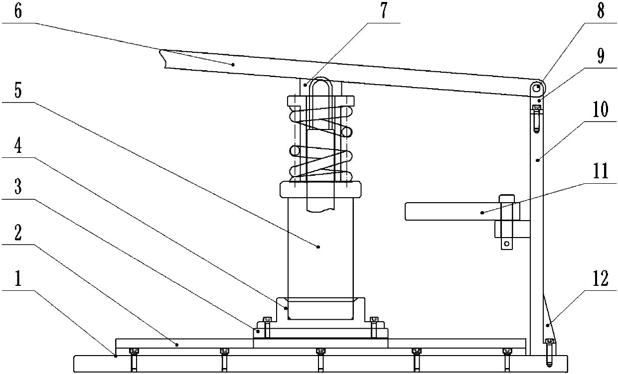
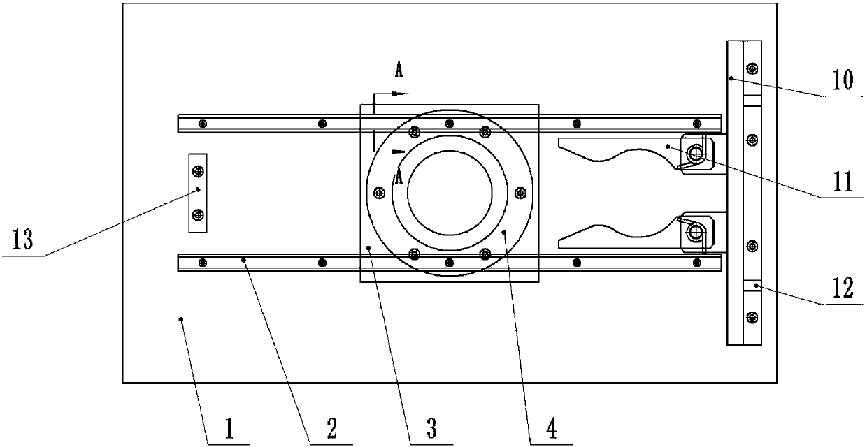
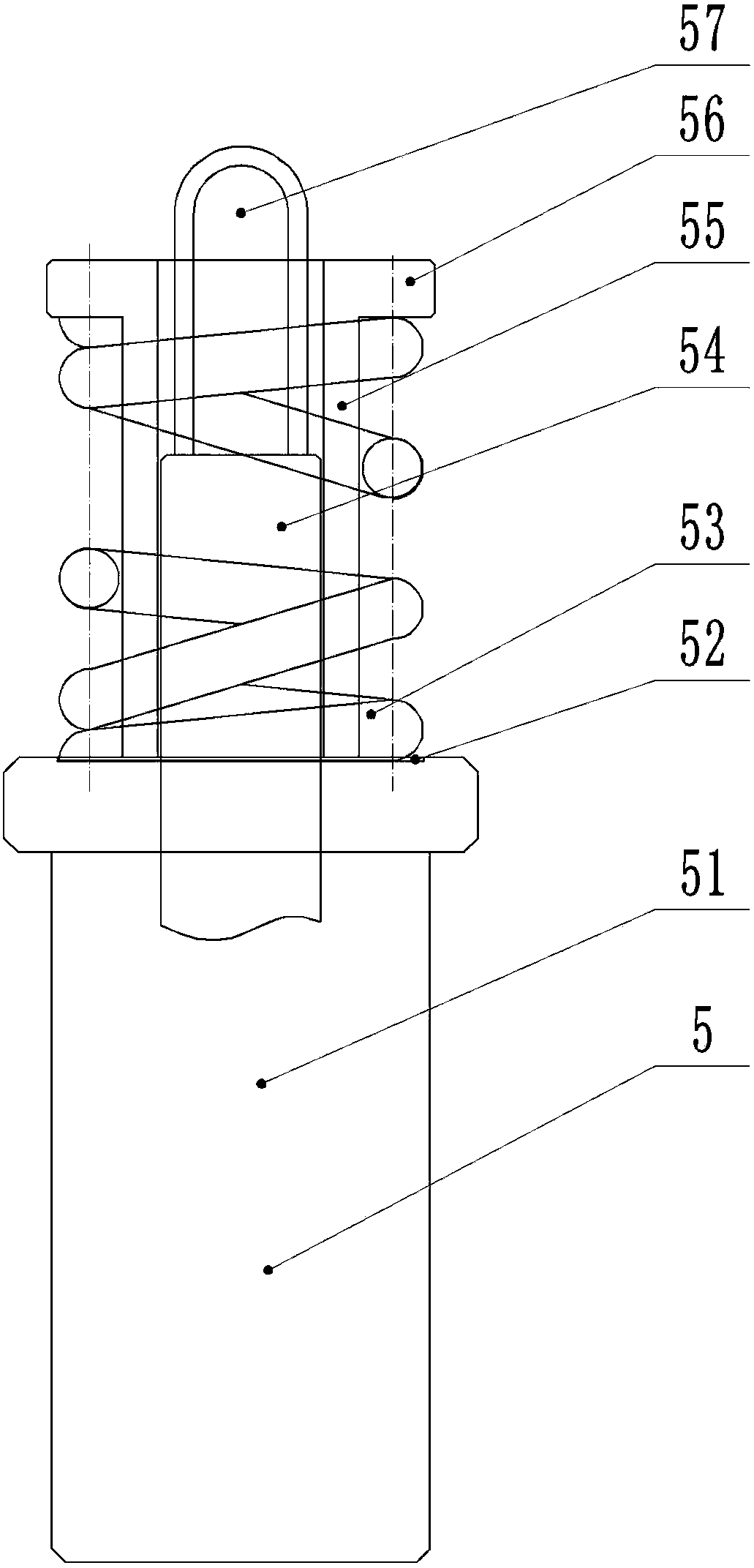
[0033] Such as Figure 1-2 As shown, the assembly device of an insulating tie rod according to the embodiment of the present invention includes: two rails 2 are laid on the workbench 1, a chassis 3 is installed on the track 2, and the insulating tie rod seat 4 is fixed on the chassis 3; the insulating tie rod seat 4 is the round platform of the middle round hole, the body 51 of the insulating pull rod 5 is placed at the round hole, and the middle round hole is chamfered to facilitate the placement of the body 51. The vertical plate 10 is fixedly installed on the right side of the workbench 1 by bolts, and a reinforcing rib 12 is installed on one side of the vertical plate 10 . The left side of workbench 1, the center of track 2 is fixed with bolt and installs stop block 13, and the height of stop block 13 is greater than the height of track 2, and chassis is spaced. The positioning mechanism 11 is installed in the middle of the vertical plate 10. The positioning mechanism 11 ...


PUM


Abstract

The invention provides an assembling device of an insulating pull rod. Two tracks are laid on a worktable; a base plate is mounted on the tracks; the insulating pull rod is fixed on the base plate; a vertical plate is mounted on one side of the worktable; a positioning mechanism is mounted in the middle of the vertical plate; the insulating pull rod keeps vertical through the positioning mechanism; two pressing rods are mounted at the upper part of the vertical plate through two hinging seats; pressing sleeves are fixed on the pressing rods; and each pressing sleeve is composed of two parts which are symmetrical from left to right. In an assembling process, the insulating pull rod is arranged in an insulating pull rod seat and moves rightwards through the tracks on the lower side until the insulating pull rod is fixed through the positioning mechanism; the pressing rods are pressed downwards, and the movable sleeve of the insulating pull rod is pressed downwards through the pressing sleeves until a connection end is exposed, and the other connector penetrates through the connection end; and the pressing rods are reset and the movable sleeve is upwards moved through an elastic force of a spring, so that assembling is finished. The assembling device of the insulating pull rod adopts a lever amplification principle, so that the labor intensity of an assembling worker is alleviated and the working efficiency is improved; and the device does not need any power and has no requirements on an assembling field.

Description

technical field [0001] The invention relates to a mechanical assembly device, in particular to an assembly device professionally used for assembling insulating pull rods. Background technique [0002] Insulating rods, also known as insulating rods, are used for closing or opening high-voltage isolating switches, for assembling and disassembling portable grounding wires, and for measuring and testing. The insulating pull rod includes an insulating rod and a joint arranged at the end of the insulating rod. A body is also provided between the insulating rod and the joint, and the insulating rod is connected to the joint through the body. Since the body is provided with a spring, when the insulating pull rod is not assembled, the spring is in a relaxed state, which covers the connection end connected to the joint on the body. Therefore, when assembling, the spring needs to be compressed to expose the connection end. At present, generally through The spring is manually compresse...

Claims


Application Information

Patent Timeline
Patent Type & Authority Patents(China)
IPC IPC(8): H01H11/00
CPCH01H11/00
Inventor 岑银富
Owner ZHEJIANG DONGCHI SWITCH
Why Eureka
Try Eureka