Package For Power Storage Device

A technology for accumulators and exterior bodies, applied in the field of exterior bodies for electric storage devices, to achieve the effects of reducing connection space, eliminating short-circuits, and preventing short-circuit accidents

Inactive Publication Date: 2016-07-20
SHOWA DENKO PACKAGING CO LTD
View PDF6 Cites 6 Cited by
  • Summary
  • Abstract
  • Description
  • Claims
  • Application Information

AI Technical Summary

Problems solved by technology

[0003] In general, laminated exteriors are thinner and lighter than metal cans, and are easy to form and seal, and are easy to handle. The exterior is exposed, so the exterior body cannot be used as a conductor like a dry battery

Method used


Image

  • Package For Power Storage Device
  • Package For Power Storage Device
  • Package For Power Storage Device

Examples


Embodiment 1

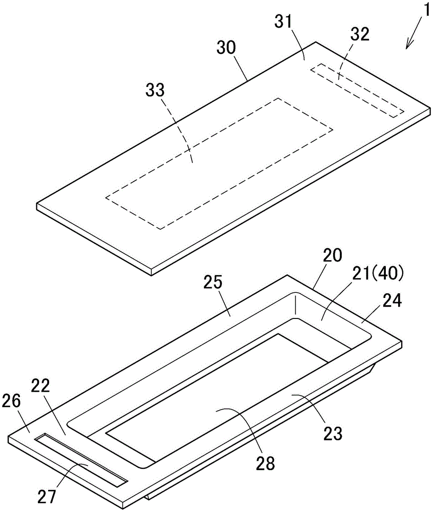
[0184] This example is referred to Figure 7A with Figure 7B The laminated exterior battery 101, refer to figure 1 , The exterior body 1 is composed of a main body 20 and a cover plate 30 .

[0185] The main body 20 is manufactured by the following method.

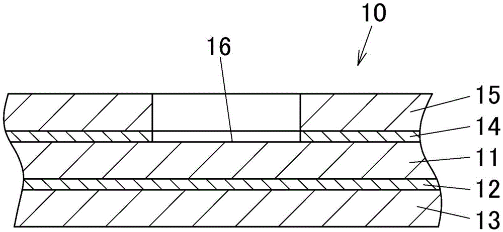
[0186] On one side of the metal foil layer 11 (aluminum foil) cut into A4 size, the coating amount after drying is 3g / m 2 Coating the adhesive 12 whose concentration was adjusted with a solvent, drying it at 100°C for 20 seconds, then laminating the heat-resistant resin layer 13, curing it in an aging oven at 40°C for three days to cure the adhesive 12 .

[0187] Such as Figure 12 As shown, after curing, stick an adhesive tape 80 of 80 mm × 80 mm on the center of the opposite surface of the metal foil layer 11 (predetermined position of the internal conductive part), and stick 80 mm at the predetermined position of the external conductive part 25 mm away from the pasting position. ×5mm tape 81( Figure 12 upper l...

Embodiment 2

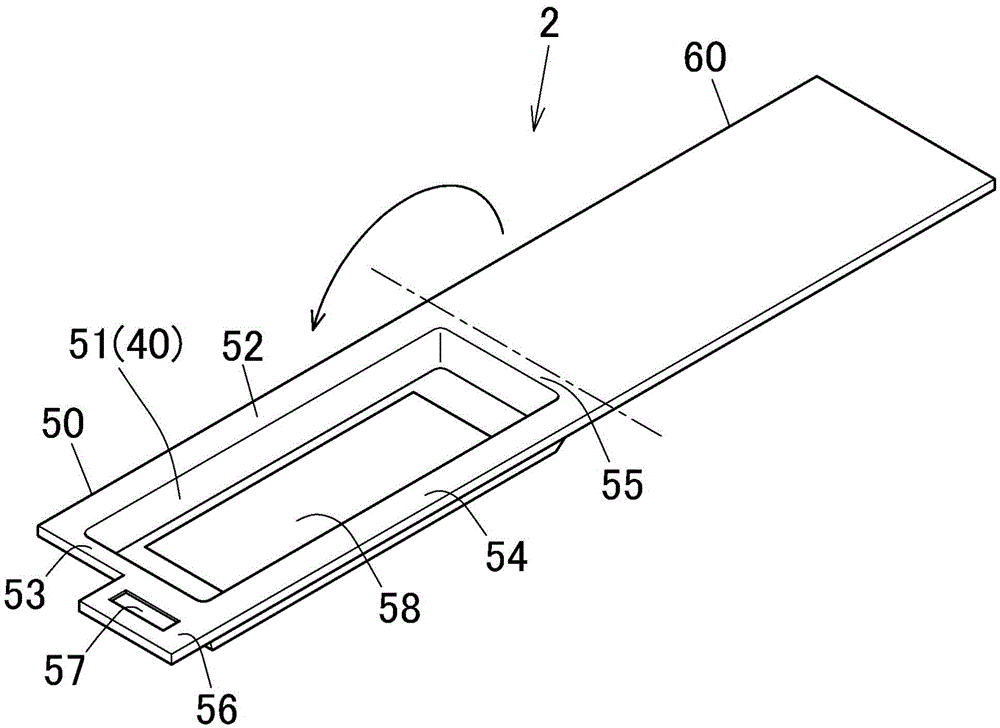
[0196] This example is referred to Figure 9A with Figure 9B of the laminated exterior battery 103, refer to Figure 4 , the exterior body 3 is composed of the main body 20 and the cover plate 35 .

[0197] The main body 20 is the same as the first embodiment.

[0198] The cover plate 35 is produced by the following method.

[0199] The laminated exterior for the cover plate 35 is performed in the same manner as the laminated exterior for the cover plate in Example 1, except that adhesive tapes 80 and 81 are attached to the surface of the metal foil layer 11 on the side of the heat-sealable resin layer 15. manufacture. This laminated exterior material was cut into 110 mm x 110 mm to obtain a cover panel 35 .

[0200] The negative electrode tab 75 was ultrasonically bonded to the negative electrode 71 of the battery body 70 and fixed.

[0201] The battery main body 70 is filled in the recess 21 of the main body 20, and the positive electrode 72 is bonded to the internal ...


PUM

PropertyMeasurementUnit
thicknessaaaaaaaaaa
thicknessaaaaaaaaaa
thicknessaaaaaaaaaa

Abstract

A package for a power storage device includes at least one laminated packaging material 1 having first and second sections. The packaging material includes a metallic foil layer, a heat-resistant resin layer, and a heat-fusible resin layer. In a state in which the heat-fusible resin layers of the first and second sections are faced, peripheral edges thereof are heat-sealed to form a storage chamber 40 for accommodating a device main body. One of the sections is extended outside the storage chamber 40 to form a conductive flange 26, 31 having an exposed heat-fusible resin layer. The conductive flange is provided with an external conductive section in which the heat-fusible resin layer is partially removed to expose the metallic foil layer. The packaging material having the external conductive section 27,32 is provided with an internal conductive section 28,33 in the storage chamber in which the heat-fusible resin layer is partially removed to expose the metallic foil layer.

Description

technical field [0001] The present invention relates to an exterior body for an electrical storage device using a laminate exterior material and related technologies. Background technique [0002] In recent years, as portable devices such as smartphones and tablet terminals have become thinner and lighter, two metal foils have been used as exterior parts for lithium-ion secondary batteries and lithium polymer secondary batteries mounted on these portable devices. The exterior body is made of a laminated exterior with a resin film bonded on one surface to replace the conventional metal can. In addition, studies have been conducted on the use of laminated exteriors for power devices such as large batteries, condensers, and capacitors used in hybrid and electric vehicles, wind power generation, solar power generation, and night-time motor storage. pieces as the material of the exterior body. [0003] In general, laminated exteriors are thinner and lighter than metal cans, and...

Claims


Application Information

Patent Timeline
Patent Type & Authority Applications(China)
IPC IPC(8): H01M2/10H01M2/20H01G2/02H01M50/119H01M50/121H01M50/129H01M50/50H01M50/536H01M50/555H01M50/562
CPCH01G2/02H01M50/50H01M50/129H01M50/536H01M50/119H01M50/555H01M50/562H01M50/121H01M10/0459Y02E60/10H01M50/124Y02P70/50H01G2/10H01M50/116H01M50/54
Inventor 南谷广治
Owner SHOWA DENKO PACKAGING CO LTD
Why Eureka
Try Eureka