Attenuator

A technology of attenuators and resistors, applied in waveguide devices, electrical components, circuits, etc., can solve problems such as limited application, difficulty in adjusting resistance and connection, and deviation of insertion loss from expected value

Inactive Publication Date: 2016-07-20
XIAN INSTITUE OF SPACE RADIO TECH
View PDF6 Cites 8 Cited by
  • Summary
  • Abstract
  • Description
  • Claims
  • Application Information

AI Technical Summary

Problems solved by technology

[0005] (1) The two grounding resistors of the π-type attenuator have a large resistance value and a long length, so the parasitic effect caused by the high-frequency microwave is relatively large, which leads to unsatisfactory simulation results obtained by calculating the theoretical resistance value and poor standing waves. The insertion loss value has a large deviation from the expected
[0006] (2) A microstrip connection is required between the three resistors, but the length and impedance of the microstrip connection itself are not included in the calculation, which further leads to poor standing waves, and the insertion loss value deviates from the expected value
[0007] (3) The three resistors are connected in π type, so it is difficult to adjust the resistance and connect them
[0008] (4) The resistance in the middle has extremely high requirements on precision, and has a great influence on standing wave and insertion loss
This causes the π-shaped attenuator to be prone to design deviation, and the resistance adjustment of the resistor is more complicated
It also limits its application in high frequency

Method used


Image

  • Attenuator
  • Attenuator
  • Attenuator

Examples


Embodiment Construction

[0025] In order to make the technical problems, technical solutions and beneficial effects solved by the present invention clearer, the present invention will be described in further detail below with reference to the accompanying drawings and embodiments. It should be understood that the specific embodiments described herein are only used to explain the present invention. , and is not intended to limit the present invention.

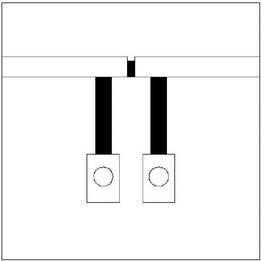
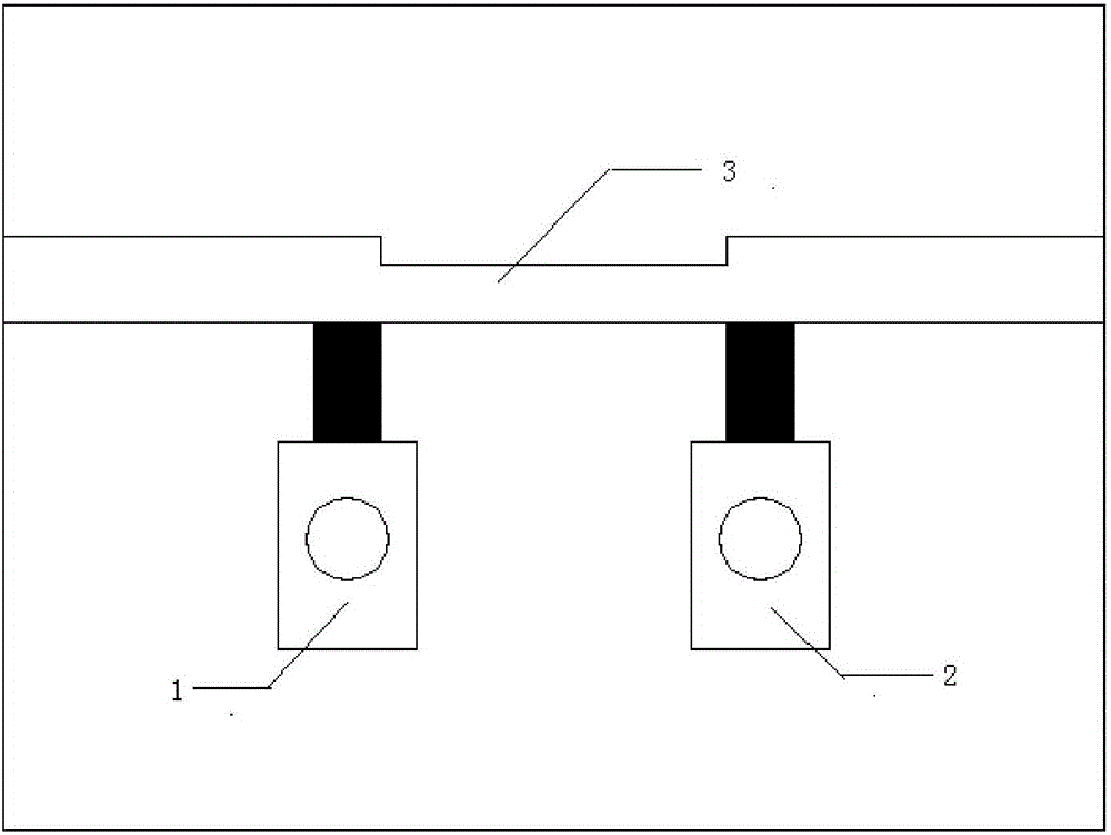
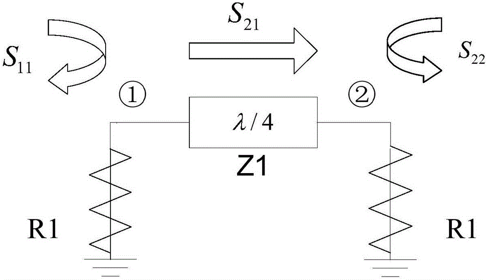
[0026] figure 2 It is a schematic diagram of the first embodiment of the attenuator in the present invention; image 3 A legend of the standing wave and insertion loss characteristics of the first embodiment of the attenuator in the present invention; Figure 4 A legend for calculating the impedance of the attenuator in the first embodiment of the attenuator in the present invention; Figure 2-Figure 4 It can be seen that the attenuator in the present invention includes a first resistor 1, a second resistor 2 and a microstrip line 3, the length of th...


PUM


Abstract

An attenuator is composed of a first resistor, a second resistor, and a micro-strip line. The length of the micro-strip line is lambda / 4, and the two ends of the micro-strip line are respectively connected with the first resistor and the second resistor. The first resistor and the second resistor are of the same resistance. Lambda is the wavelength corresponding to the center frequency of the attenuator. The attenuator of invention has the characteristics of simple structure, flexible design and compact structure, can adapt to the requirement of high bands, can be applied to various needed circuits and systems, and can be easily generalized to other bands, especially high bands. A series of difficulties in high-frequency application of attenuators are solved.

Description

technical field [0001] The present invention relates to an attenuator, in particular to an attenuator using a microstrip line, in particular to an attenuator with smaller parasitic parameters and lower precision requirements. Background technique [0002] Traditional MIC circuit attenuators include π-type attenuators and T-type attenuators. Among them, the π-type attenuator is widely used. However, it has many shortcomings in thin-film circuits and microwave high-frequency circuits, which limit its scope of application and frequency of use. [0003] figure 1 is the schematic diagram of the π-type attenuator model; figure 1 The resistance of the π-type attenuator in the 11 <-16dB, where S 11 is the reflection coefficient of the input port. [0004] Its main shortcomings and deficiencies are: [0005] (1) The resistance of the two grounding resistances of the π-type attenuator is large and the length is long, so the parasitic effect caused by the high frequency of th...

Claims


Application Information

Patent Timeline
IPC IPC(8): H01P1/22
CPCH01P1/22
Inventor 杨飞朱正贤孙树峰杨军
Owner XIAN INSTITUE OF SPACE RADIO TECH
Why Eureka
Try Eureka