
Mobile terminal and antenna of same

A mobile terminal and antenna technology, which is applied in the field of mobile terminals, can solve the problems that the metal frame cannot be integrated, the cycle and cost cannot be avoided, and the radio frequency performance of the antenna is not good, so as to speed up development, debugging and finalization, and save layout Space, convenient and flexible effect of debugging

Active Publication Date: 2016-07-20
BYD CO LTD
View PDF3 Cites 5 Cited by
  • Summary
  • Abstract
  • Description
  • Claims
  • Application Information

AI Technical Summary

Problems solved by technology

[0006] The disadvantages of solution 1 in the above-mentioned related technologies are: the traditional antenna design and production process are still used, and there is no cost saving; more importantly, the metal frame cannot be well integrated with the antenna. This has a considerable negative impact on the radio frequency performance of the antenna, resulting in poor radio frequency performance of the antenna
[0007] The shortcomings of the second solution in the above-mentioned related technologies are: it is difficult to debug the antenna. This is because the second solution uses the segmented metal frame to directly feed the antenna. When the size of the metal frame is not suitable for antenna resonance and radiation, it is impossible to manually Debugging (because the increase and shortening of the metal frame size is difficult to change manually), and if the prototype is modified, the cycle and cost are unavoidable problems

Method used


Image

  • Mobile terminal and antenna of same
  • Mobile terminal and antenna of same
  • Mobile terminal and antenna of same

Examples


Embodiment Construction

[0028] Embodiments of the present invention are described in detail below, examples of which are shown in the drawings, wherein the same or similar reference numerals designate the same or similar elements or elements having the same or similar functions throughout. The embodiments described below by referring to the figures are exemplary only for explaining the present invention and should not be construed as limiting the present invention.

[0029] The following disclosure provides many different embodiments or examples for implementing different structures of the present invention. To simplify the disclosure of the present invention, components and arrangements of specific examples are described below. Of course, they are only examples and are not intended to limit the invention. Furthermore, the present invention may repeat reference numerals and / or letters in different instances. This repetition is for the purpose of simplicity and clarity and does not in itself indicat...


PUM


Abstract

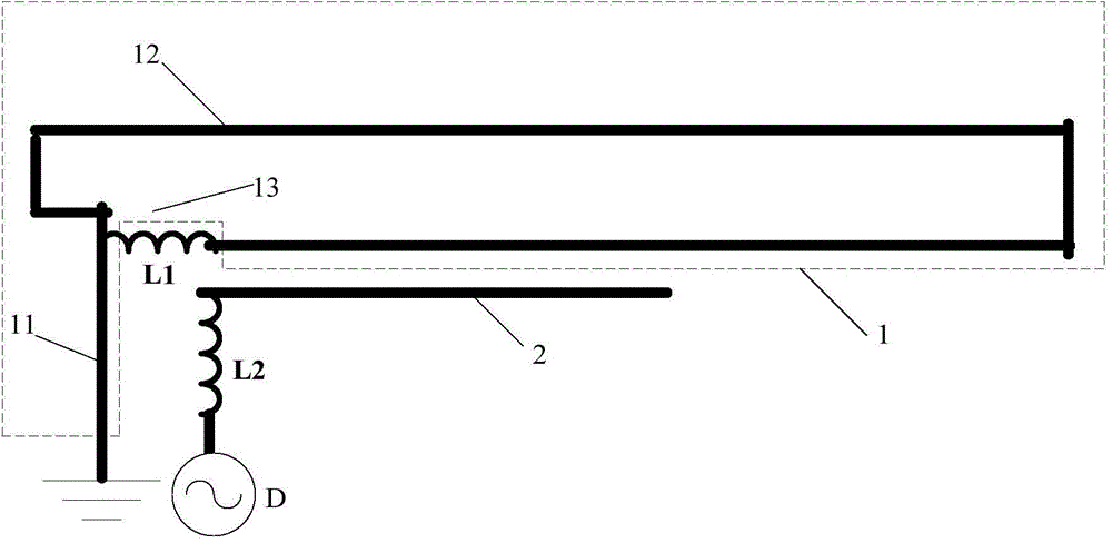
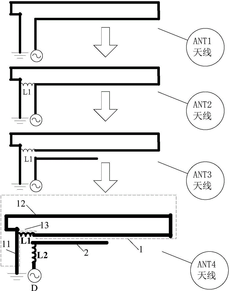
The invention discloses a mobile terminal. The mobile terminal comprises a shell, a printed wiring board, a metal frame, a first connector, a second connector and a first antenna, wherein the metal frame encircles the shell and comprises a first frame, a second frame and a third frame, the first frame is provided with a first gap, the first connector is connected with the first frame on the first gap, the second connector is connected with the third frame and a ground end of the printed wiring board separately, the first antenna comprises a first antenna main radiation body, a first part, a second part, a first inductor, a third part, a fourth part and a fifth part, the first part parallel to the first frame is connected with the first connector, the second part parallel to the third frame is connected with the first part, the first inductor is connected with the second part and the ground end of the printed wiring board separately, the third part is arranged under the second part and is parallel to the second part, one end of the third part is suspended, the fourth part parallel to the first part is connected with a second inductor and the third part separately, and the fifth part parallel to the first part is connected with the second inductor and a first feeding end of the printed wiring board separately. By the mobile terminal, the antenna cost is reduced, and the mobile terminal is convenient and flexible to debug. The invention also discloses an antenna of the mobile terminal.

Description

technical field [0001] The present invention relates to the technical field of mobile terminals, in particular to a mobile terminal and an antenna for the mobile terminal. Background technique [0002] Due to the beautiful metal texture, mobile phones with metal frames are more and more sought after by various mobile phone companies. However, due to the significant suppression effect of the metal frame around the antenna on the antenna radiation, the antenna design of the corresponding mobile phone is significantly more difficult. [0003] For LTEDiversity (diversity) antennas, GPS (Global Positioning System, Global Positioning System) antennas, and BT (BlueTooth, Bluetooth) & WLAN (WirelessLocalAreaNetwork, wireless local area network) antennas in 4GLTE (LongTermEvolution, long-term evolution, the fourth-generation mobile antenna standard) mobile phones , there are generally the following two solutions in related technologies: [0004] Solution 1 is the mainstream solution...

Claims


Application Information

Patent Timeline
Patent Type & Authority Applications(China)
IPC IPC(8): H01Q1/44H01Q1/36H01Q1/50H04M1/02
Inventor 郭庆余
Owner BYD CO LTD
Learn More