Supercharge Your Innovation With Domain-Expert AI Agents!

Calibrate a CMM with a calibration laser head at the tool center point

A coordinate measuring machine and laser head technology, applied in the field of calibration data, can solve expensive and time-consuming problems, achieve low maintenance costs, improve accuracy and efficiency, and reduce costs

Active Publication Date: 2019-12-31
HEXAGON TECH CENT GMBH
View PDF12 Cites 0 Cited by
  • Summary
  • Abstract
  • Description
  • Claims
  • Application Information

AI Technical Summary

Problems solved by technology

[0016] Here, too, the entire calibration is quite a complex process (setting the laser tracker at different positions and performing the corresponding measurements at the same CMM position), a major disadvantage of this calibration method is that the calibration should be performed by specially trained the fact that people execute
Moreover, providing this method is comparatively very expensive and time consuming, since at least one precise laser tracking device is required and this device should be placed at positions known with varying precision
Alternatively, more than one laser tracker is provided, making the method even more expensive

Method used


Image

  • Calibrate a CMM with a calibration laser head at the tool center point
  • Calibrate a CMM with a calibration laser head at the tool center point
  • Calibrate a CMM with a calibration laser head at the tool center point

Examples


Embodiment approach

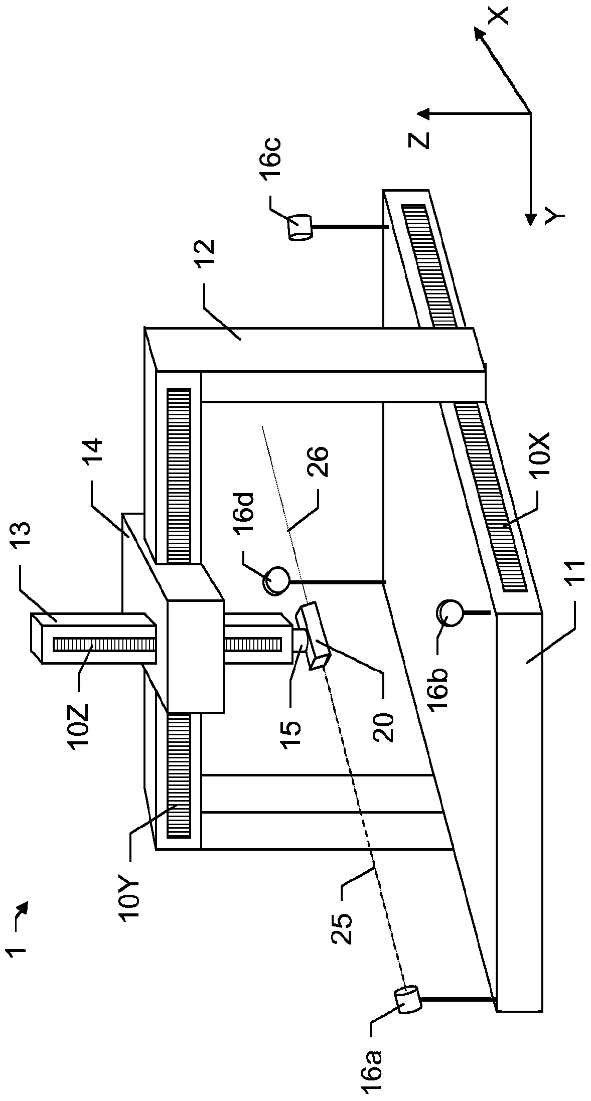
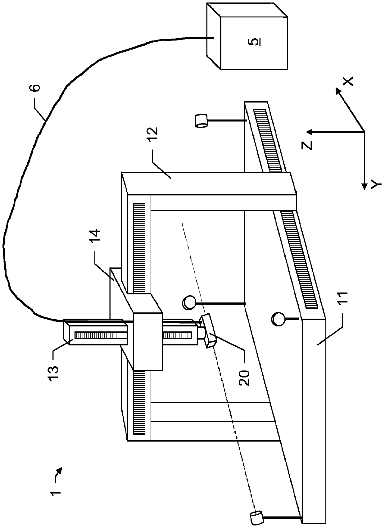
[0085] exist figure 1 In , an exemplary embodiment of a gantry coordinate measuring machine 1 (CMM) according to the invention is depicted, the coordinate measuring machine 1 comprising a base 11 and comprising means for coupling a tool carrier 15 (probe 15) to the base 11 A frame structure comprising several frame parts 12, 13, 14 movable relative to one another. The first frame part 12 is a mast with two mast legs connected at their upper ends by a bridge. Driven by a drive mechanism (not shown), the frame member 12 is movable along the longitudinal sides of the base 11 . This direction corresponds to the first direction X. The movement of the frame part 12 is in particular carried out by a toothed rack attached to the base 11 , which meshes with a pinion on the frame part 12 , but can alternatively be realized according to solutions known from the prior art.

[0086] The carriage 14 is arranged movably on the bridge of the frame part 12 . The movement of the carriage 14...


PUM


Abstract

Calibration method for a coordinate measuring machine (1), the coordinate measuring machine (1) comprising a drive mechanism for moving a tool carrier (15) relative to a base (11) for approaching a measurement point and comprising a calibration laser head (20) implemented so and attached to the tool carrier (15) so that a laser beam (25), which is emittable by the calibration laser head (20,21), is swivelable around at least two basically perpendicular axes (X,Y,Z) and changes in distance are measurable interferometrically by means of the calibration laser head (20). A set of retro-reflectors (16a-d) is arranged in fixed positions relative to and / or onto the base (11). The method comprises emitting and directing the laser beam (25) towards a first of the set of retro-reflectors (16a-d), whereby a measuring path (26) is defined by the orientation of the laser beam (25), moving the calibration laser head (20) along the measuring path (26) so that the laser beam (25) is kept directed towards the first retro-reflector (16a) according to the measuring path (26) and the reflected laser beam is continuously received at the calibration laser head (20), measuring the change in distance to the first retro-reflector (16a) at a plurality of measuring positions along the measuring path (26) and gathering a machine position for each of the plurality of measuring positions, the machine position relating to a position of the tool carrier (15) relative to the base (11).

Description

technical field [0001] The present invention generally relates to a method for generating calibration data for a coordinate measuring machine (CMM) by means of a guided laser emitting unit and several stationary retroreflectors, wherein the distance between the laser emitter and the corresponding retroreflector is determined. distance changes. Background technique [0002] It is common practice to inspect the workpiece after production is complete on a coordinate positioning device such as a coordinate measuring machine (CMM) in order to check the correctness of predetermined object parameters, such as the size and shape of the object. [0003] In a conventional three-dimensional coordinate measuring machine, the probe is supported for movement along three mutually perpendicular axes (in directions X, Y and Z). Thus, the probe can be guided to any arbitrary point within the space of the measurement volume of the coordinate measuring machine and the object can be measured by...

Claims


Application Information

Patent Timeline
IPC IPC(8): G01B21/04B23Q17/22
CPCG01B21/042B23Q17/22G01B5/008
Inventor C·艾斯利帕斯卡尔·乔迪尔
Owner HEXAGON TECH CENT GMBH
Features
  • R&D
  • Intellectual Property
  • Life Sciences
  • Materials
  • Tech Scout
  • Unparalleled Data Quality
  • Higher Quality Content
  • 60% Fewer Hallucinations
Learn More