
Stiffening component and method for manufacturing a stiffening component

A component and basic unit technology, which is applied in the field of strengthening components and for manufacturing strengthening components, and can solve the problems of difficult to manufacture crystalline morphological structures.

Active Publication Date: 2016-07-27
AIRBUS OPERATIONS GMBH
View PDF7 Cites 21 Cited by
  • Summary
  • Abstract
  • Description
  • Claims
  • Application Information

AI Technical Summary

Problems solved by technology

Crystalline morphology structures have so far been difficult to fabricate

Method used


Image

  • Stiffening component and method for manufacturing a stiffening component
  • Stiffening component and method for manufacturing a stiffening component
  • Stiffening component and method for manufacturing a stiffening component

Examples


Embodiment Construction

[0051] In the drawings, identical reference numerals denote identical or functionally identical components, unless otherwise stated. Directional terms such as "top", "bottom", "left", "right", "upper", "lower", "horizontal", "vertical", "front", "rear" and similar terms are used only These are for illustrative purposes and are not intended to limit the embodiments to the particular arrangements shown in the figures.

[0052] While specific embodiments have been illustrated and described herein, those skilled in the art will recognize that various alternative and / or equivalent implementations may be used in place of that illustrated and described without departing from the scope of the invention. specific example of . Generally, this application is intended to cover any adaptations or variations of the specific embodiments discussed herein.

[0053] Additive Manufacturing (ALM), Selective Laser Sintering (SLS) and Free Solid Fabrication (SFF) technologies, commonly referred t...


PUM


Abstract

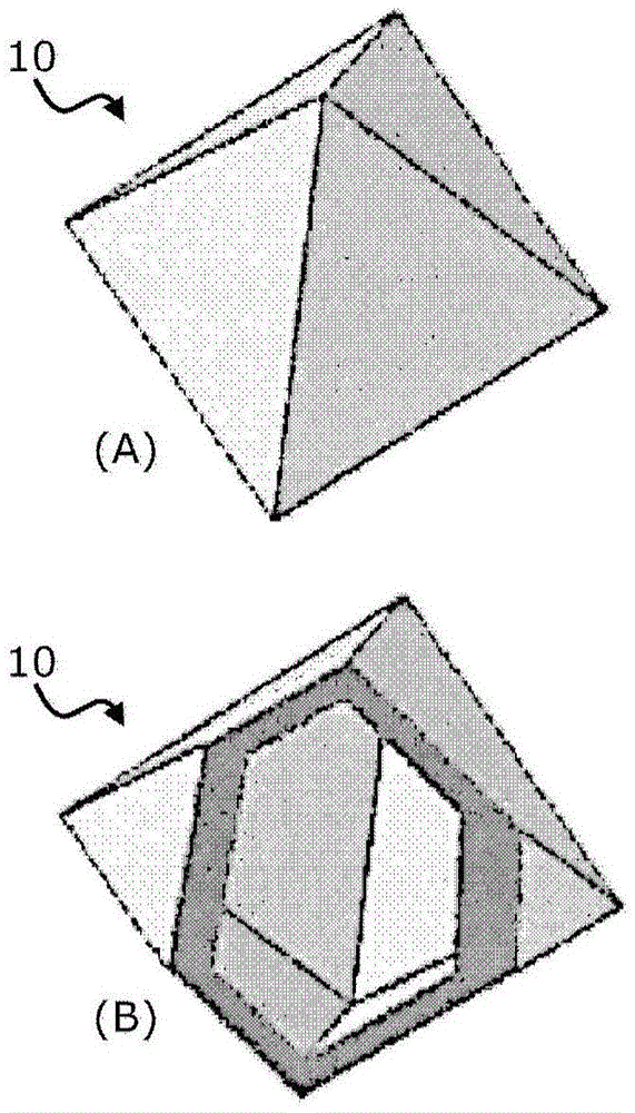
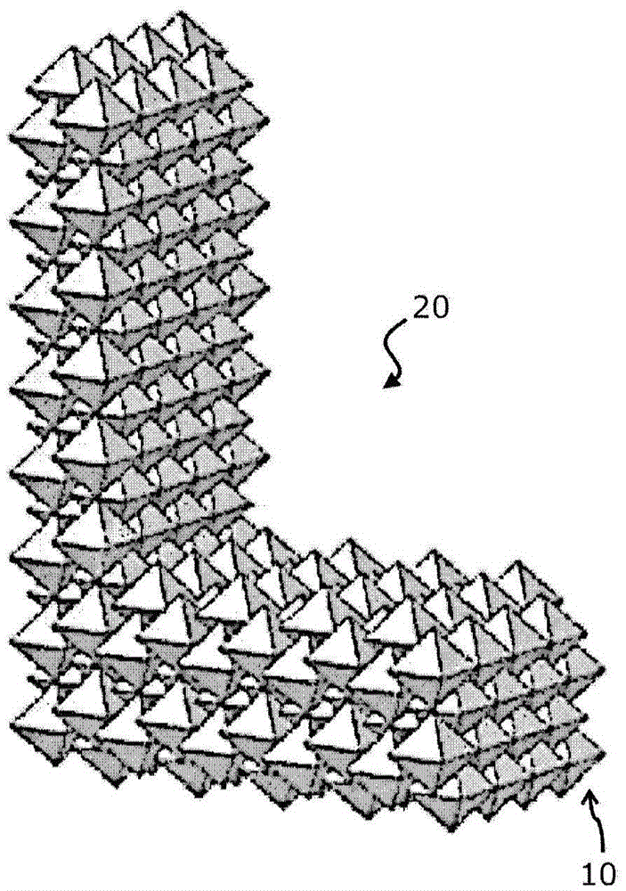
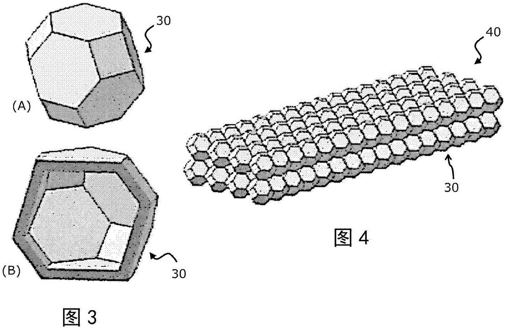
The present invention relates to a stiffening component and a method for manufacturing a stiffening component. A component includes elementary units arranged in a regular pattern to form a mesoscopic geometrical structure, wherein each of the plurality of elementary units has the shape of a hollow polyhedron. A method for manufacturing such a component includes manufacturing elementary units in a regular pattern to form a mesoscopic geometrical structure using an AM or 3D printing technique.

Description

technical field [0001] The present invention relates to a reinforced component and a method for manufacturing a reinforced component, in particular using additive layer manufacturing (ALM), fused deposition modeling (FDM), selective laser sintering (SLS) and / or free-body fabrication (SFF) processes Methods. Background technique [0002] In modern aircraft and spacecraft, fibre-reinforced composite structures are commonly employed, which may include a core structure sandwiched between outer plies to increase the stiffness of the resulting part, insulate said part, or simply provide Stability and support in the third dimension. Such core structures are generally designed as porous or hollow structures by including voids, empty cells or air pockets or pockets in the material forming the core structure. By providing a non-solid core structure, the weight of the overall component can be reduced, thereby reducing the load on the aircraft and, as a result, reducing the fuel consu...

Claims


Application Information

Patent Timeline
IPC IPC(8): B22F3/11B22F3/115B22F5/10B28B1/00B29C67/00B33Y10/00B33Y80/00
CPCB22F3/11B22F3/115B22F5/10B28B1/001B22F10/18B22F10/12B22F10/25B22F10/20B22F10/28B29D24/005B29D99/0089B33Y80/00B22D25/02B29C64/188Y02P10/25B33Y10/00B33Y50/02B22F3/1017B22F5/00B22F2998/10
Inventor 沃尔克·罗布瑞特伯恩德·鲁珀特朱利安·谢里曼
Owner AIRBUS OPERATIONS GMBH
Learn More