
Hydraulic lifting-type pipe perforator

A hydraulic lifting and punching machine technology, which is applied in the direction of boring/drilling, drilling/drilling equipment, metal processing machinery parts, etc. It can solve the problems of uncontrollable drill bit drilling, complicated drill bit mechanism, and low drilling efficiency. Problems, to achieve the effect of simple structure, strong operability, and improve processing efficiency

Inactive Publication Date: 2016-07-27
CHENGDU MATSUKAWA METAL MATERIALS
View PDF9 Cites 4 Cited by
  • Summary
  • Abstract
  • Description
  • Claims
  • Application Information

AI Technical Summary

Problems solved by technology

[0003] The purpose of the present invention is to provide a hydraulic lifting type pipe punching machine to achieve the purpose of changing the moving mechanism of the pipe punching machine, improving the operating efficiency and facilitating operation, and solving the problem of low punching efficiency and high drilling efficiency of the existing pipe punching machines. The drill bit mechanism of the hole is relatively complicated and it is impossible to control whether the drill bit drills through the hole of the pipe

Method used


Image

  • Hydraulic lifting-type pipe perforator

Examples


Embodiment Construction

[0010] The present invention will be described in further detail below through specific implementation examples and in conjunction with the accompanying drawings.

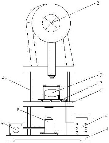
[0011] figure 1 It shows a structural schematic diagram of a pipe punching machine with a lifting device provided by the present invention, including a body 1, a processing part 2 and a clamping part 3 located on the body 1, and the feature is that the processing part 2 is a pipe punching machine. The drill part of the hole machine, the clamping part 3 is the part that clamps the pipe to be processed; the supporting guide post 4 is connected between the processing part 2 and the clamping part 3; the clamping part 3 is fixedly connected with a support plate 5 , the support plate 5 and the support guide post 4 are slidingly arranged, and the two sides of the support plate 5 are provided with holes matching the support guide post 4; the bottom of the support plate 5 is fixedly connected with a lifting device that driv...


PUM


Abstract

The invention discloses a hydraulic lifting-type pipe perforator, belonging to the technical field of pipe perforators. The hydraulic lifting-type pipe perforator comprises a machine body and a machining part and a clamping part located on the machine body, and is characterized in that supporting guide posts are connected between the machining part and the clamping part; a supporting plate is fixedly connected with the clamping part; a sliding device is arranged among the supporting plate and the supporting guide posts; a lifting device which is used for driving the supporting plate to slide is fixedly connected onto the lower part of the supporting plate; the lifting device is connected with a controller; the controller is provided with a distance sensor; and the distance sensor is located on one side, close to the machining part, of the supporting plate. By adopting the hydraulic lifting-type pipe perforator, the problems of a current pipe perforator that the perforation efficiency is low; a perforation drill bit structure is relatively complexed; and whether a drill bit drills through a hole in a pipe cannot be controlled are solved.

Description

technical field [0001] The invention relates to the technical field of pipe punching machines, in particular to a hydraulic lifting type pipe punching machine. Background technique [0002] Pipes are widely used in our daily life. Pipes have a wide range of uses. During the use of pipes, it is often necessary to punch holes on the outer surface of the pipes to meet the processing and use of pipes; the existing pipes are punched There are many types of pipe punching machines. Some pipe punching machines can punch pipes individually, and some pipe punching machines can simultaneously punch holes on the outer circular surface of pipes. Existing pipe punching machines, especially small pipe punching machines Hole drilling machines generally drill holes in fixed pipes through the movement of the drill bit, and the drill bit is connected with a power device that drives its rotation, so the operator needs to manually shake the entire drill power device to realize the drilling of th...

Claims


Application Information

Patent Timeline
Patent Type & Authority Applications(China)
IPC IPC(8): B23B41/00B23B47/22
CPCB23B41/00B23Q5/26
Inventor 周建川
Owner CHENGDU MATSUKAWA METAL MATERIALS
Learn More