

Plasma hole cutting equipment
A plasma and hole-cutting technology, which is applied in plasma welding equipment, welding/cutting auxiliary equipment, welding equipment, etc., can solve the problems of high price and achieve the effect of fast cutting speed, smooth cutting surface and small thermal deformation
- Summary
- Abstract
- Description
- Claims
- Application Information
AI Technical Summary
Problems solved by technology
Method used
Image

Examples
Embodiment Construction
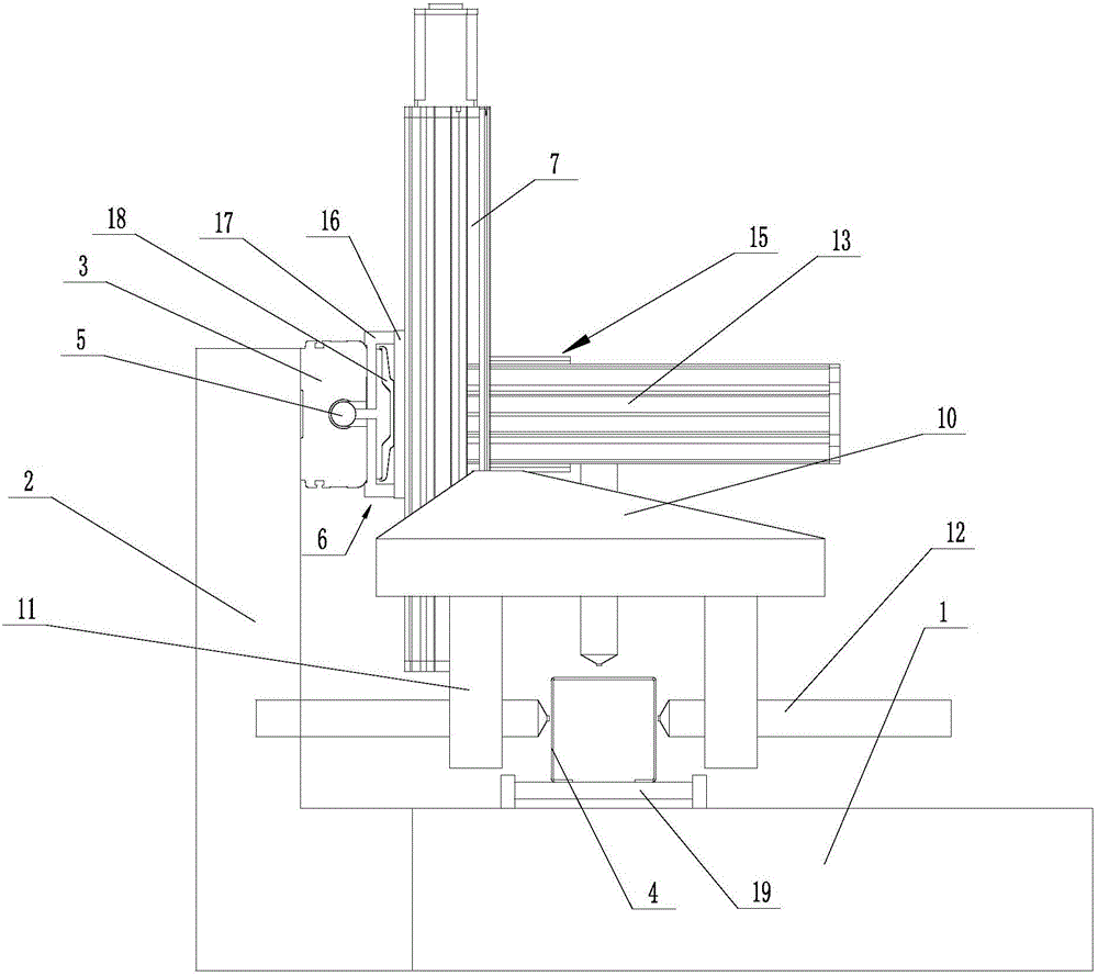
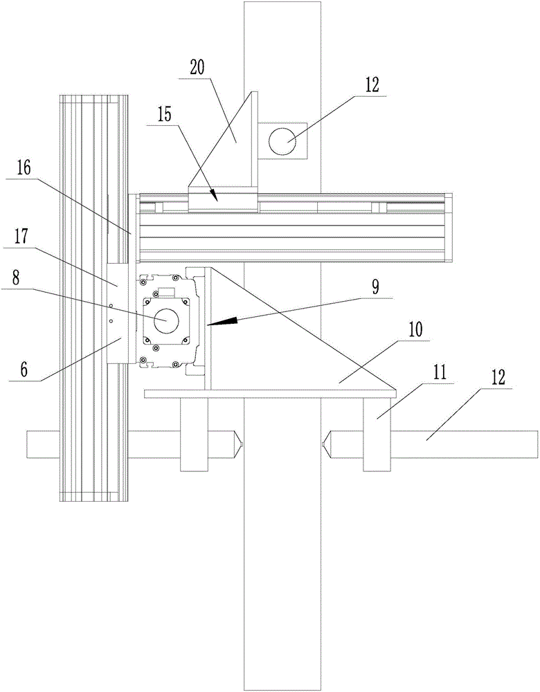
[0012] Specific embodiments of the present invention will be described in detail below in conjunction with the accompanying drawings.
[0013] Such as figure 1 As shown, the plasma hole cutting equipment of the present invention comprises a base 1, and a support 2 is arranged on one side of the base 1, and an X support 3 is arranged on the support 2, and the X support 3 is connected with the workpiece on the base 1 (square The conveying direction of the tube 4) is parallel, the X-pillar 3 is provided with an X-axis 5 that moves axially along the X-pillar 3 , and the outside of the X-pillar 3 is provided with an X-slider 6 that moves axially along the X-pillar 3 , and the X-axis 5 and the X The slider 6 is fixedly connected, and the X slider 6 is also fixed with a vertical Y pillar 7. The Y pillar 7 is provided with a Y axis 8 that moves axially along the Y pillar 7, and the outside of the Y pillar 7 is provided with a shaft along the Y pillar 7. The Y slider 9 that moves axia...
PUM
 Abstract
Description
Claims
Application Information