Resistor and wire welding device and method thereof

A technology for welding devices and resistance wires, applied in auxiliary devices, welding equipment, auxiliary welding equipment, etc., can solve the problems of high labor intensity, low welding efficiency, and low quality, so as to improve welding efficiency and quality, reduce labor costs and The effect of labor intensity

Active Publication Date: 2016-07-27
重庆金燕巢科技有限公司
View PDF4 Cites 3 Cited by
  • Summary
  • Abstract
  • Description
  • Claims
  • Application Information

AI Technical Summary

Problems solved by technology

The disadvantages of manual welding are: low weld

Method used


Image

  • Resistor and wire welding device and method thereof
  • Resistor and wire welding device and method thereof
  • Resistor and wire welding device and method thereof

Examples


Embodiment Construction

[0043] The specific embodiments of the present invention will be further described below in conjunction with the accompanying drawings.

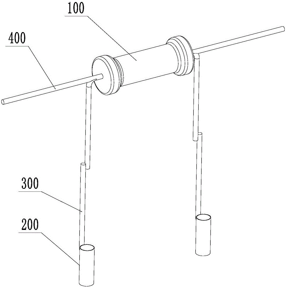
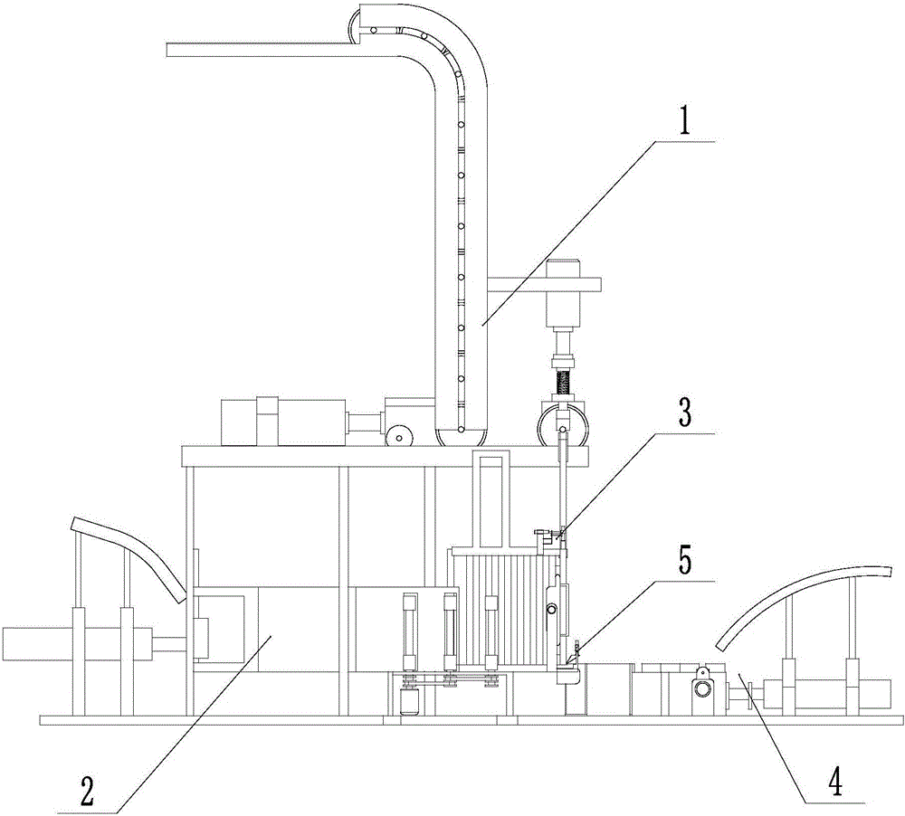
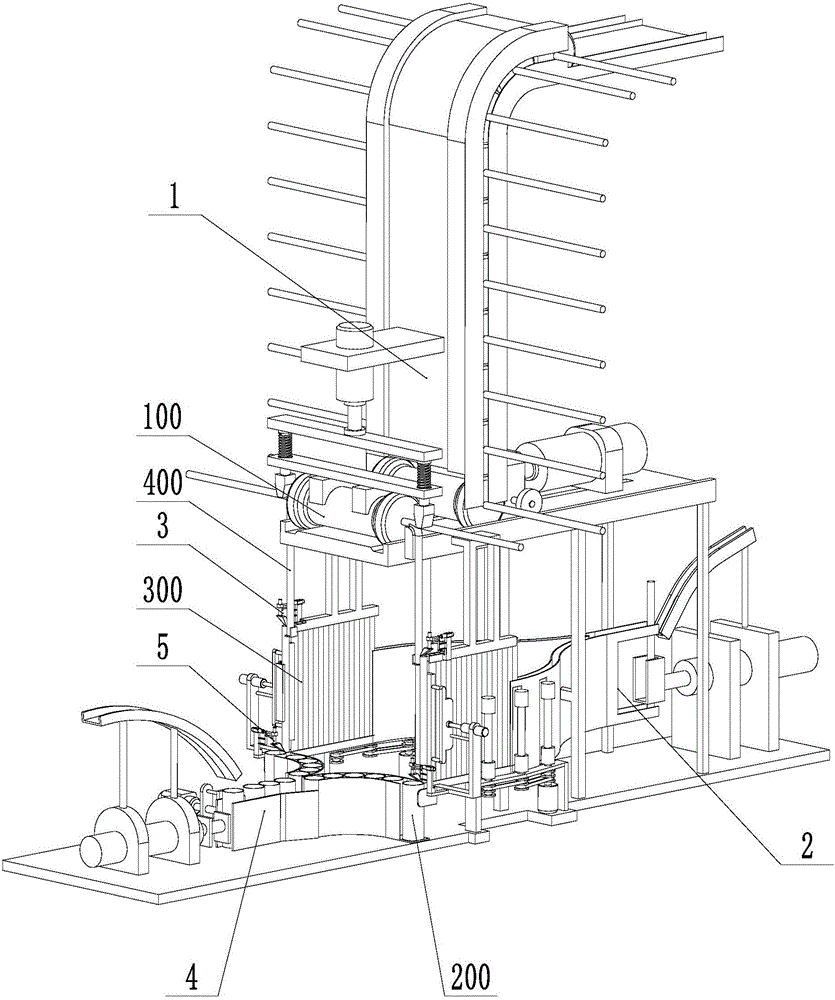
[0044] Such as figure 2 , image 3 As shown, the welding device of the resistance and the wire of the present embodiment includes a resistance conveying and bending device 1, a wire conveying device 2, a resistance wire welding device 3, a copper pipe conveying device 4 and a wire copper pipe welding device 5, and a wire conveying device 2 and the copper pipe conveying device 4 are located below the resistance conveying and bending device 1, and the resistance wire welding device 3 and the wire copper pipe welding device 5 are respectively located at both ends of the wire 300. The resistance conveying and bending device 1 conveys and bends the resistance 100, the wire conveying device 2 conveys the wire 300, and the wire 300 and the resistance wire 400 of the resistance 100 after bending merge to the resistance wire welding device 3 for we...


PUM


Abstract

The invention relates to a resistor and wire welding device. The resistor and wire welding device comprises a resistor conveying and bending device, a wire conveying device and a resistor and wire welding device body; the wire conveying device is located below the resistor conveying and bending device, and the resistor and wire welding device body is located at the upper end of a wire; the resistor conveying and bending device comprises a supporting plate, and a resistor conveying assembly, a resistor pushing assembly and a resistor bending assembly are mounted on the supporting plate; the wire conveying device comprises a wire guide assembly, a wire push-in assembly located at the front end of the wire guide assembly and a wire positioning assembly located at the rear end of the wire guide assembly, and the wire positioning assembly is located under the resistor bending assembly; and the resistor wire welding device is located at the contact position between the lower end of the bent resistance wire and the upper end of the wire.

Description

technical field [0001] The invention relates to the field of circuit board production equipment, in particular to welding equipment for circuit board resistance, copper pipes and wires. Background technique [0002] Such as figure 1 As shown, the resistance (100) and the copper pipe (200) used on the circuit board need to be welded together by wires (300). The current welding method is manual welding. When welding, the resistance wires at both ends of the resistance (100) (400) bending, after bending, the end of the resistance wire (400) is welded with one end of the wire (300), and the other end of the wire (300) is welded with the copper pipe (200). The disadvantages of manual welding are: low welding efficiency, low quality, and high labor intensity. Contents of the invention [0003] In view of the above-mentioned shortcomings of the prior art, the applicant conducts research and improvement, and provides a welding device and method for resistance and wire, which rea...

Claims


Application Information

Patent Timeline
IPC IPC(8): B23K37/00B23Q7/00
CPCB23K37/00B23Q7/00
Inventor 张惠莹
Owner 重庆金燕巢科技有限公司
Why Eureka
Try Eureka