Upright iron core rolling machine

A coiled iron core, vertical technology, applied in the manufacture of inductors/transformers/magnets, other manufacturing equipment/tools, accessories of shearing machines, etc. , difficult to place and other problems, to ensure the quality of rolling, high work efficiency, labor saving effect

Active Publication Date: 2016-07-27
沈阳特变电工电气工程有限公司
View PDF5 Cites 4 Cited by
  • Summary
  • Abstract
  • Description
  • Claims
  • Application Information

AI Technical Summary

Problems solved by technology

The iron core of this traditional reactor has low working efficiency and is not easy to place
With the update of the product, the new type of reactor needs a new type of iron core, the diameter requires φ2100mm, the width requires 300mm, and the weight is about 7 tons; the iron core of this type of reactor needs to be rolled and placed, but this is not yet possible. Rolling of reactor core

Method used


Image

  • Upright iron core rolling machine
  • Upright iron core rolling machine
  • Upright iron core rolling machine

Examples


Embodiment Construction

[0029] The present invention will be described in further detail below in conjunction with the accompanying drawings.

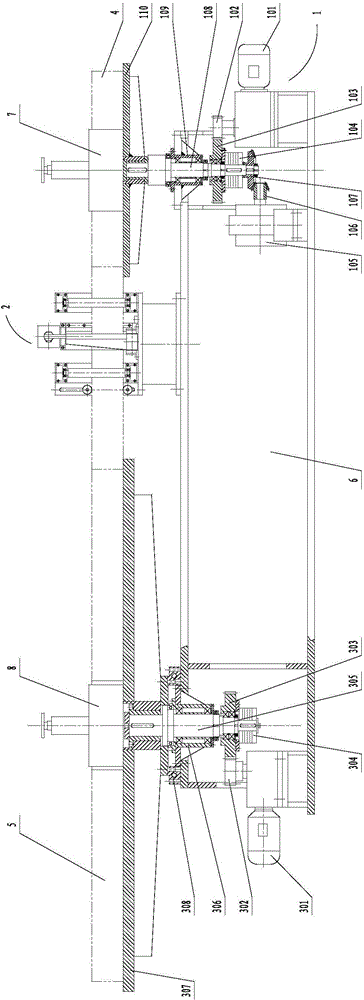
[0030] Such as figure 1 As shown, the present invention comprises unwinding machine 1, shearing machine 2, coiling machine 3, bed 6, coil material tensioning device 7 and workpiece tensioning tire 8, wherein unwinding machine 1, shearing machine 2 and coiling machine 3 are respectively installed on the bed 6, and the shearing machine 2 is located between the unwinding machine 1 and the coiling machine 3.

[0031] The discharge machine 1 includes a first reducer 101, a discharge machine transmission mechanism, a magnetic material brake 105, a first bevel gear 106, a second bevel gear 107, a discharge machine shaft 108, a first bearing seat 109 and a discharge machine working Table 110, the unwinding machine transmission mechanism includes the first pinion gear 102, the first large gear 103 and the first electromagnetic clutch 104, the unwinding machine shaft ...


PUM

PropertyMeasurementUnit
diameteraaaaaaaaaa

Abstract

The invention belongs to the field of electric reactor iron cores, and particularly provides an upright iron core rolling machine which comprises a machine body, a feeding device, a shearing machine and a rolling device. A feeding device shaft in the feeding device is rotatably mounted on the machine body and connected with a first reducer mounted on the machine body through a feeding device transmission mechanism. A feeding device workbench for bearing rolled materials is mounted at one end of the feeding device shaft, and a rolled material supporting unit is arranged on the feeding device workbench. The other end of the feeding device shaft is connected with a magnetic material brake used for providing tension for the rolling device for rolling iron cores. A rolling device shaft in the rolling device is rotatably mounted on the machine body, a rolling device workbench is mounted at one end of the rolling device shaft, a workpiece supporting tyre is arranged on the rolling device workbench, and the other end of the rolling device shaft is connected with a second reducer mounted on the machine body through a rolling device transmission mechanism. The shearing machine is located between the feeding device and the rolling device. By means of the upright iron core rolling machine, the iron cores of novel electric reactors are rolled, work efficiency is high, labor is saved, and the rolled workpieces fully meet the quality requirement.

Description

technical field [0001] The invention belongs to the field of reactor iron cores, in particular to a vertical iron core winding machine. Background technique [0002] In the power system, the reactor plays an important role. The iron core of the traditional reactor is cut into a very poor shape to form a sector, and then a circle is surrounded by multiple sectors. The iron core of this traditional reactor has low working efficiency and is not easy to place. With the update of the product, the new type of reactor needs a new type of iron core, the diameter requires φ2100mm, the width requires 300mm, and the weight is about 7 tons; the iron core of this type of reactor needs to be rolled and placed, but this is not yet possible. Rolling of reactor core. Contents of the invention [0003] The object of the present invention is to provide a vertical iron core rolling machine, which meets the current coiling requirements of reactor iron cores. [0004] The purpose of the pre...

Claims


Application Information

Patent Timeline
Patent Type & Authority Applications(China)
IPC IPC(8): B23P23/04B23D15/08B23D33/02B21D11/06B21D11/22H01F41/02
Inventor 王德琮
Owner 沈阳特变电工电气工程有限公司
Why Eureka
Try Eureka