Eureka AIR delivers breakthrough ideas for toughest innovation challenges, trusted by R&D personnel around the world.

Hydraulic lift dam

A technology of hydraulic lifting dam and hydraulic cylinder, applied in the field of hydraulic lifting dam, can solve the problems of low reliability and safety of hydraulic dam, water leakage of hydraulic dam, inability to achieve dam surface leveling, etc., so as to avoid water leakage at the bottom, installation and maintenance operations The effect of convenience, improved reliability and safety

Inactive Publication Date: 2016-07-27
储斌
View PDF6 Cites 0 Cited by
  • Summary
  • Abstract
  • Description
  • Claims
  • Application Information

AI Technical Summary

Problems solved by technology

However, after the movable slab of the hydraulic dam is lowered, the movable slab is higher than the top of the fixed embankment, and the dam surface cannot be flush with the river bed, which may easily cause water leakage at the bottom of the hydraulic dam, making the reliability and safety of the hydraulic dam lower

Method used


Image

  • Hydraulic lift dam
  • Hydraulic lift dam

Examples


Embodiment Construction

[0016] In order to make the technical means, creative features, goals and effects achieved by the present invention easy to understand, the present invention will be further described below in conjunction with specific illustrations.

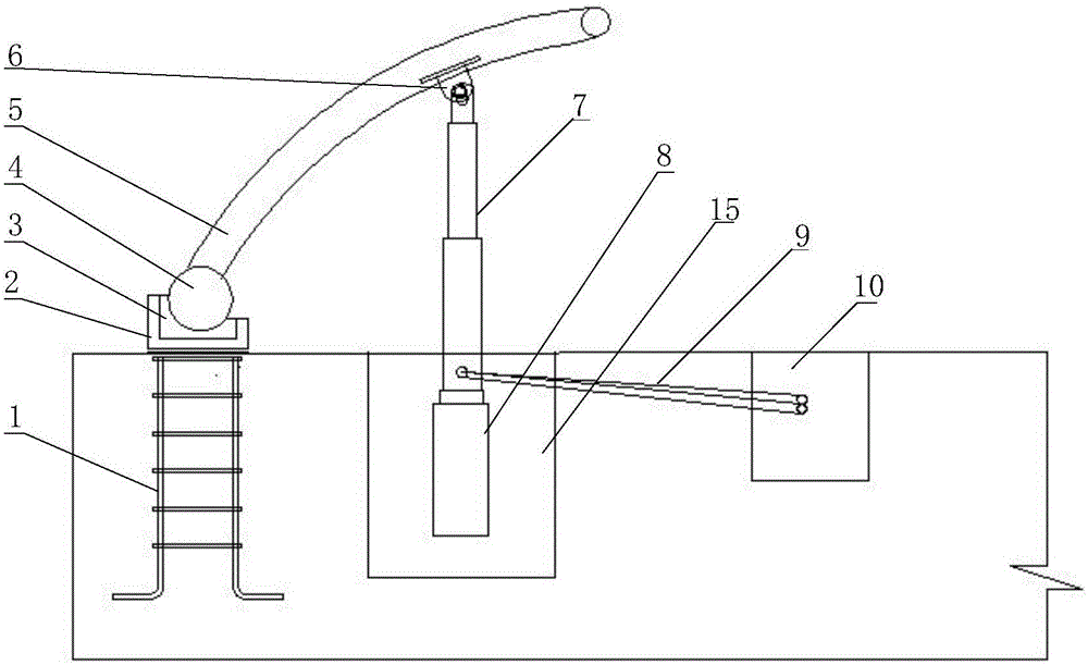
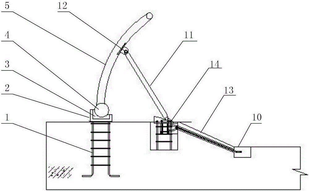
[0017] During specific implementation, combined with Figure 1-2 , a hydraulic lifting dam, including steel ground anchor 1, embedded steel channel 2, water-stop rubber 3, concentric shaft 4, movable plate 5, lug 6, hydraulic rod 7, hydraulic cylinder 8, oil pipe 9, hydraulic station 10. Support rod 11, lug 12, slideway 13, limit device 14, hydraulic cylinder groove 15.

[0018] A hydraulic lifting dam, the pre-embedded steel channel 2 is fixedly installed on the reinforced ground anchor 1, and the pre-embedded steel channel 2 can be fixed on the reinforced ground anchor 1 in the form of welding. The concentric shaft 4 is movably installed in the embedded steel channel 2. In order to avoid water leakage, a water-stop rubber 3 is installed betwe...


PUM

PropertyMeasurementUnit
Heightaaaaaaaaaa
Heightaaaaaaaaaa

Abstract

The invention discloses a hydraulic lift dam which comprises a rebar ground anchor, a pre-embedded steel tank, a concentric shaft, a movable plate, a hydraulic cylinder and a hydraulic cylinder container, wherein the pre-embedded steel tank is fixedly mounted on the rebar ground anchor; the concentric shaft is mounted in the pre-embedded steel tank; the movable plate is fixedly connected with the concentric shaft; the hydraulic rods of the hydraulic cylinder are movably connected with the movable plate; the hydraulic cylinder is vertically mounted in the hydraulic cylinder container; the hydraulic rods of the hydraulic cylinder perform vertical lifting motion; and the hydraulic cylinder is connected with a hydraulic station through an oil pipe. The hydraulic lift dam provided by the invention has the advantages that the hydraulic cylinder is vertically mounted in the hydraulic cylinder container, so that the hydraulic rods of the hydraulic cylinder can perform vertical lifting motion, and then the movable plate can be in flush with or lower than a river bed; water-stop rubber is mounted between the concentric shaft and the pre-embedded steel tank, so that the bottom of the hydraulic lift dam can be effectively protected from water leakage, and the reliability and the safety of the hydraulic lift dam can be improved; and furthermore, the hydraulic lift dam has the advantages of being simple in structure, and convenient to mount, repair and operate.

Description

technical field [0001] The invention relates to the technical field of hydraulic dam design, in particular to a hydraulic lifting dam. Background technique [0002] The hydraulic dam is a new type of water storage device, which has a significant effect on water storage. The overall cost of hydraulic dams is lower than that of sluice gates and rubber dams of the same specification. During the high water season of the hydraulic dam, nothing can be seen on the riverbed, which will neither affect flood control nor navigation, and there is no need to build ship locks. However, after the movable plate of the hydraulic dam is put down, the movable plate is higher than the top of the fixed embankment, and the dam surface cannot be flush with the river bed, which easily causes water leakage at the bottom of the hydraulic dam, making the reliability and safety of the hydraulic dam lower. Contents of the invention [0003] In order to overcome the defects of the prior art of the ab...

Claims


Application Information

Patent Timeline
IPC IPC(8): E02B7/40E02B7/42E02B7/54
CPCE02B7/40E02B7/42E02B7/54
Inventor 储斌
Owner 储斌
Why Eureka
Eureka Blog
Learn More