A multi-stage single-double control flow regulating switch valve

A technology of flow adjustment and single-dual control, which is applied in the field of bathroom industry, can solve the problems of inability to adjust flow or combined adjustment, missing flow adjustment parts, etc., and achieve the effect of simple structure, improved hand feeling and more stability

Active Publication Date: 2018-01-16
FUJIAN XIHE SANITARY WARE TECHNOLOGY CO LTD
View PDF6 Cites 0 Cited by
  • Summary
  • Abstract
  • Description
  • Claims
  • Application Information

AI Technical Summary

Problems solved by technology

[0002] Existing traditional push switch valves generally only have a single function, most of which are water diversion functions, switching different water outlet states, but lacking a flow adjustment part, it is impossible to adjust the flow or combined adjustment of any water channel in use. Therefore, there is an urgent need for a breakthrough Conventional and traditional on-off valves with flow regulation to meet the needs of the market

Method used


Image

  • A multi-stage single-double control flow regulating switch valve
  • A multi-stage single-double control flow regulating switch valve
  • A multi-stage single-double control flow regulating switch valve

Examples


Embodiment 1

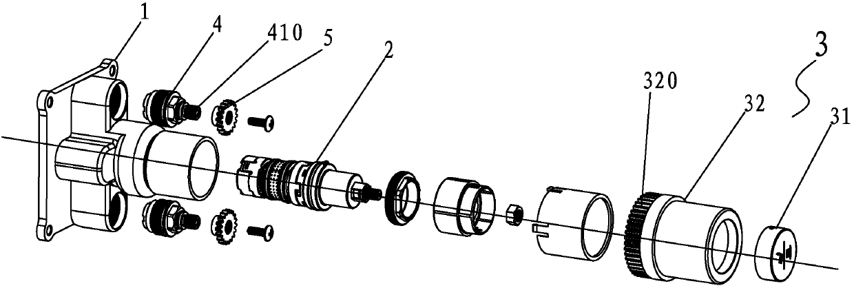
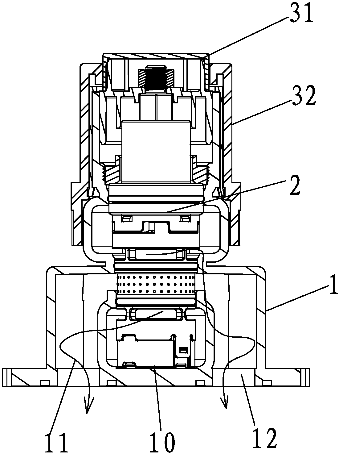
[0044] Example one, such as Figure 1 to Figure 9 As shown, the multi-stage single and double control flow adjustment switch valve in this embodiment mainly includes the following parts: valve body 1, water diversion valve core 2, pressing key 31, adjusting sleeve 32, driving gear 51, and driving rod 41 and sealing water piston 42;

[0045] When assembling, press the component 3 part, the pressing key 31 and the adjusting sleeve 32 are integrally formed or fixedly connected, so that the adjusting sleeve 32 moves and moves together with the pressing key 31;

[0046] In the flow adjustment assembly 4 part, the drive rod 41 and the sealing water piston 42 are connected by a threaded connection, so that the drive rod can drive the sealing water piston 42 to move up and down along the drive rod 41; then install the assembled flow adjustment assembly 4 into the valve Inside the body 1, and corresponding to the respective outlets 11 and 12;

[0047] Multi-level switching structure 5, in wh...

Embodiment 2

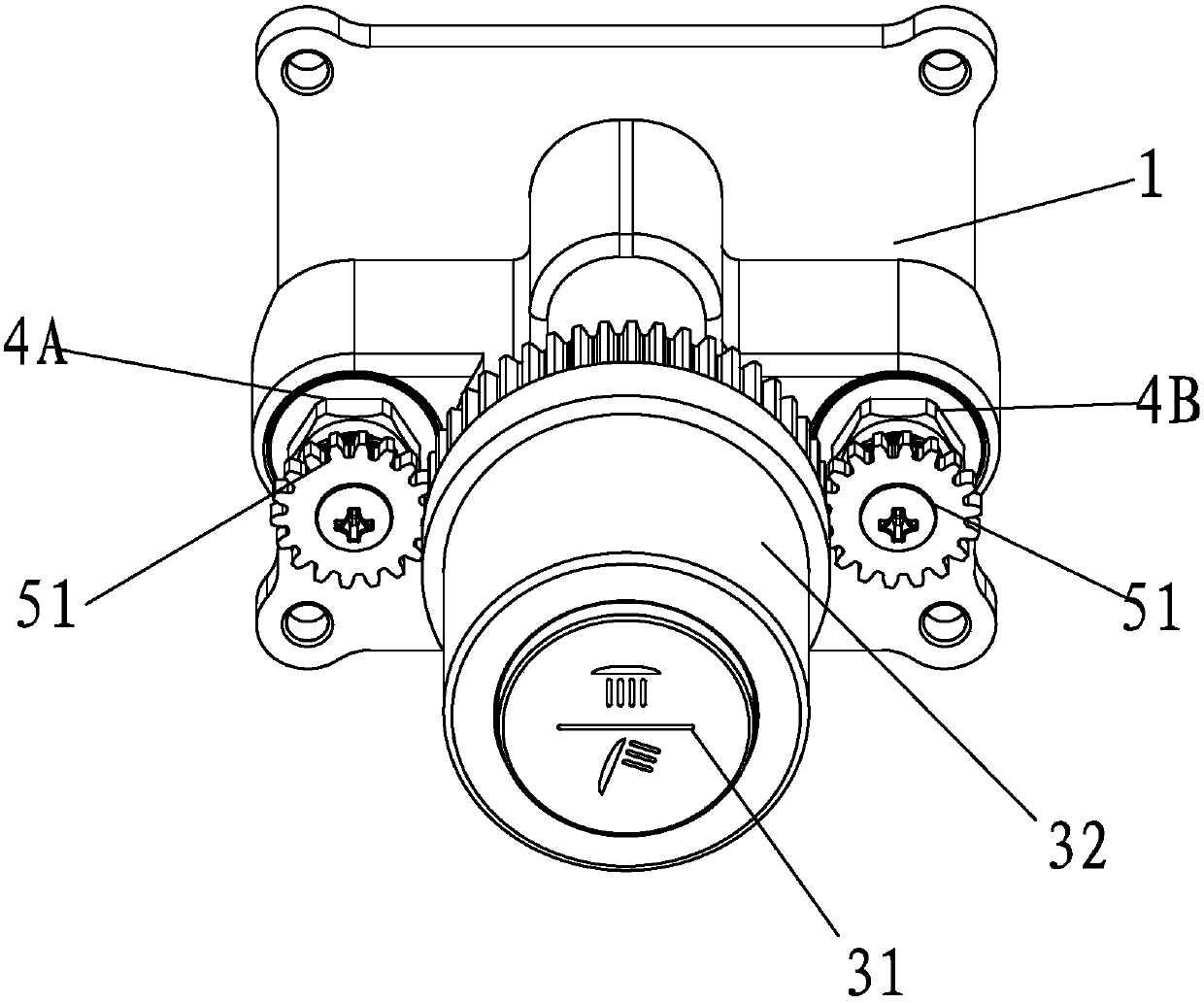
[0050] Example two, such as Figure 1 to Figure 10 As shown, the multi-stage single and double control flow adjustment switch valve described in the second embodiment mainly includes the following parts: valve body 1, water diversion valve core 2, pressing key 31, adjusting sleeve 32, driving gear 51, driving The rod 41 and the water-sealing piston 42; the same parts in this embodiment as in the first embodiment will not be repeated, the difference is that the pressing key 31 and the adjusting sleeve 32 of the pressing component 3 part are arranged separately; the drive gear 51 is immediately assembled when assembling Assembled with two flow regulating components 4A, 4B;

[0051] In actual use, such as Figure 9 to Figure 11 As shown, when the pressing component 3 is pressed, the upper pressing key 31 independently opens the water diversion valve core 2 and forms any water path or water path to be opened, and the regulating sleeve 32 has the first and second flow regulating compon...

Embodiment 3

[0054] Example three, such as Figure 1 to Figure 11 As shown, the multi-stage single and double control flow adjustment switch valve described in the third embodiment mainly includes the following parts: valve body 1, water diversion valve core 2, pressing key 31, adjusting sleeve 32, driving gear 51, driving The rod 41 and the water-sealing piston 42; in this embodiment, the same parts as the first and second embodiments will not be repeated. The difference is that the pressing key 31 of the pressing component 3 and the adjusting sleeve 32 are integrally arranged, but three are formed Switching position, that is, the adjusting sleeve 32 is first engaged with the first flow adjusting component 4A for independent adjustment, and then pressed to the next switching position, that is, the linkage portion 320 on the adjusting sleeve 32 and the first and second flow adjusting components 4A, 4B Engage at the same time to form a simultaneous adjustment mode; pressing down makes the ad...


PUM


Abstract

The invention discloses a multi-stage single-dual-control flow regulation switch valve. The multi-stage single-dual-control flow regulation switch valve comprises a valve body and a shunting valve core, wherein the valve body is provided with a water inlet and at least two water outlets, and the shunting valve core is arranged in the valve body. The multi-stage single-dual-control flow regulation switch valve is characterized by further comprising a pressing assembly, flow regulation assemblies and multi-stage switching structures, wherein the pressing assembly is arranged in the valve body, is connected with the shunting valve core, and is used for driving the shunting valve core to switch the water inlet to communicate with any effluent water; the flow regulation assemblies are arranged in the valve body; the multi-stage switching structures are used for connection and cooperation between the pressing assembly and the flow regulation assemblies; each of the multi-stage switching structures comprises a regulation member and a linkage part which are matched with the flow regulation assemblies, and besides, height difference is formed between the regulation members; the linkage parts are shaped in the pressing assembly. The multi-stage single-dual-control flow regulation switch valve provided by the invention is simple in structure and easy to realize, and not only realizes the functions of a conventional pressing switch, but also can have flow regulation functions, and besides, the flow regulation functions can be in discretionary combination and use.

Description

Technical field [0001] The invention relates to the sanitary ware industry, in particular to a multi-stage single and double control flow regulating switch valve. Background technique [0002] The existing traditional push-switch valves generally have only a single function, most of which are water diversion functions, which switch different water outlet states, and lack the flow adjustment part. It is impossible to adjust the flow or combination of any water channels in use. Therefore, a break is urgently needed. Conventional and traditional on-off valves with flow adjustment to meet market demand. Summary of the invention [0003] The purpose of the present invention is to solve the existing problems and provide a multi-stage single and double control flow adjustment switch valve, which has a simple structure and is easy to implement. It not only realizes the existing push switch function, but also satisfies the flow adjustment function. The adjustment function can be used in a...

Claims


Application Information

Patent Timeline
Patent Type & Authority Patents(China)
IPC IPC(8): F16K11/14F16K31/53F16K1/36
CPCF16K1/36F16K11/14F16K31/53
Inventor 林孝发林孝山
Owner FUJIAN XIHE SANITARY WARE TECHNOLOGY CO LTD
Why Eureka
Try Eureka