A waste combustion heat energy utilization device

A technology of waste combustion and thermal energy, applied in the direction of combustion method, combustion type, combined combustion mitigation, etc., can solve problems such as thermal energy waste

Inactive Publication Date: 2018-07-20
SINOBIOWAY BIOENVIRONMENT CO LTD
View PDF6 Cites 0 Cited by
  • Summary
  • Abstract
  • Description
  • Claims
  • Application Information

AI Technical Summary

Problems solved by technology

At present, the ash will be discharged directly, and the bricks will be made after cooling. The discharge of the ash will take away a lot of heat energy; at the same time, the exhaust gas generated by the combustion chamber will also take away a lot of heat energy, resulting in waste of heat energy.

Method used


Image

  • A waste combustion heat energy utilization device

Examples


Embodiment Construction

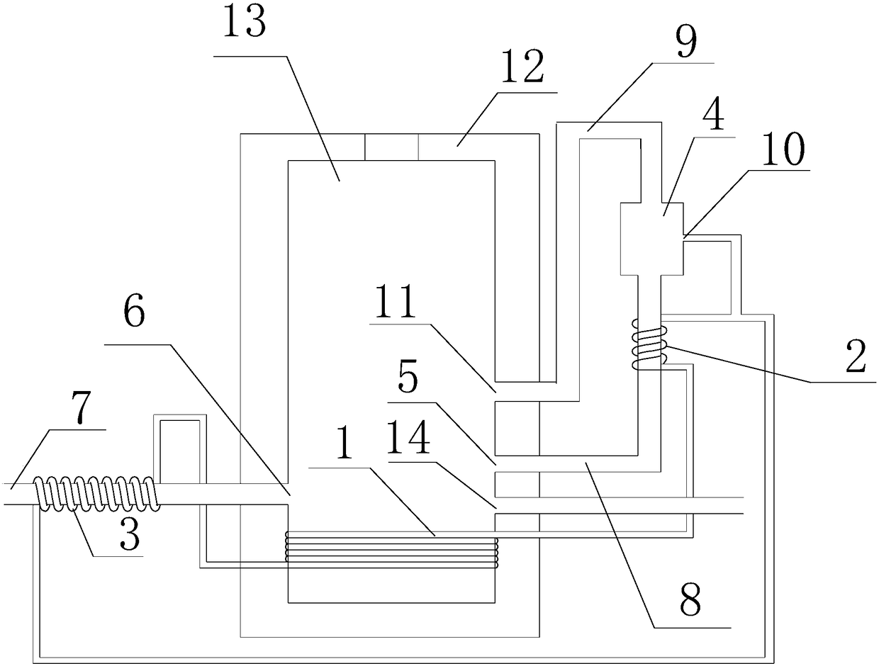
[0015] Such as figure 1 as shown, figure 1 The utility model proposes a garbage combustion heat energy utilization device.

[0016] refer to figure 1 , the waste combustion heat energy utilization device proposed by the present invention includes: a combustion cavity 13, an air intake channel 8, an exhaust gas channel 7 and a housing 12;

[0017] The combustion cavity 13 is located in the casing 12, and the garbage in the combustion cavity forms a dry layer, a reduction layer, an oxidation layer and an ash layer in sequence from the top to the bottom;

[0018] The side wall of the combustion chamber 13 is provided with a first air inlet 5 and a second air inlet 14, the air intake channel 8 communicates with the inside of the combustion chamber 13 through the first air inlet 5, and the side wall of the combustion chamber 13 is provided with a second air inlet 14. An air outlet 6, the first air inlet 5, the second air inlet 14 and the first air outlet 6 are all communicated w...


PUM


Abstract

The invention discloses a garbage combustion heat energy utilization device. The garbage combustion heat energy utilization device comprises a combustion cavity, a gas inlet channel, a tail gas channel and a shell; the combustion cavity is located in the shell, a first gas inlet is formed in the side wall of the combustion cavity, and a first gas outlet is formed in the side wall; a draught fan is arranged at the position of the first gas outlet; a second gas outlet is formed in the side wall of the combustion cavity; the second gas outlet is communicated with the gas inlet through a first pipeline, and a condenser is arranged on the first pipeline; a first spiral pipeline surrounding the outer wall of the combustion cavity is arranged on the combustion cavity; a second spiral pipeline surrounding the gas inlet channel is arranged on the periphery of the gas inlet channel; a third spiral pipeline surrounding the tail gas channel is arranged on the periphery of the tail gas channel; and the first end of the first spiral pipeline is in pipeline communication with the first end of the third spiral pipeline, the second end of the third spiral pipeline is in pipeline communication with the first end of the second spiral pipeline, and the second end of the second spiral pipeline is in pipeline communication with the second end of the first spiral pipeline.

Description

technical field [0001] The invention relates to the technical field of garbage treatment, in particular to a garbage combustion heat utilization device. Background technique [0002] With the development of the economy and the acceleration of urbanization, the amount of municipal solid waste generated every year has doubled. Garbage incineration is a better treatment method. Through burning, not only the volume of garbage is greatly reduced, but also the heat generated by burning can be used to generate electricity and generate heat to achieve the purpose of energy recovery. The ash after incineration can be used to make bricks. In the prior art, the combustion chamber can be used to pyrolyze and incinerate the garbage. During the combustion process, the garbage will go through the processes of drying, reduction, and oxidation in the combustion chamber and finally form ash, that is, the garbage will form a dry residue in the combustion chamber. layer, reduced layer, oxide l...

Claims


Application Information

Patent Timeline
Patent Type & Authority Patents(China)
IPC IPC(8): F23G5/46
CPCF23G5/46F23G2206/203Y02E20/12
Inventor 曹文波明永刚李启仁舒志强
Owner SINOBIOWAY BIOENVIRONMENT CO LTD
Why Eureka
Try Eureka