Carbon dioxide air-conditioning system and gas-liquid separator thereof

A gas-liquid separator and carbon dioxide technology, applied in refrigeration and liquefaction, compressors, refrigeration components, etc., can solve the problems of complex structure, inconvenient installation, difficulty in producing qualified products, etc., achieve good heat exchange effect, easy to realize, The effect of simple structure

Inactive Publication Date: 2016-07-27
ZHEJIANG SANHUA AUTOMOTIVE COMPONENTS CO LTD
View PDF7 Cites 13 Cited by
  • Summary
  • Abstract
  • Description
  • Claims
  • Application Information

AI Technical Summary

Problems solved by technology

[0009] In order to realize heat exchange, the pipes used for flowing low-temperature and low-pressure refrigerants and high-temperature and high-pressure refrigerants are designed with sleeves. This kind of structure is complicated and requires too much technology, so it is difficult to produce qualified products. The inner pipe body 151b and the outer pipe Leakage easily occurs between bodies 151a
[0010] In addition, the high-temperature and high-pressure inlet pipe, high-temperature and high-pressure outlet pipe, low-temperature and low-pressure inlet pipe, and low-temperature and low-pressure outlet pipe are all inserted into the head 125 of the gas-liquid separator, which is inconvenient to install and has poor sealing performance.

Method used


Image

  • Carbon dioxide air-conditioning system and gas-liquid separator thereof
  • Carbon dioxide air-conditioning system and gas-liquid separator thereof
  • Carbon dioxide air-conditioning system and gas-liquid separator thereof

Examples


Embodiment Construction

[0045] In order to enable those skilled in the art to better understand the technical solutions of the present invention, the present invention will be further described in detail below in conjunction with the accompanying drawings and specific embodiments.

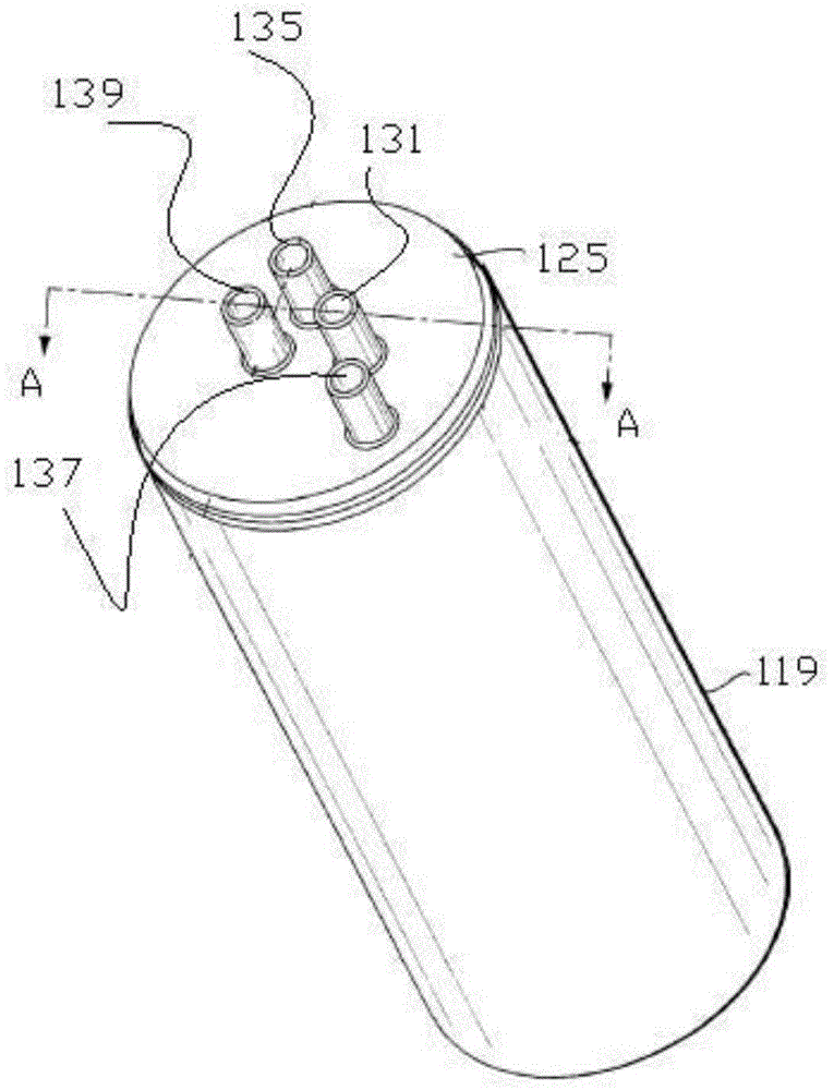
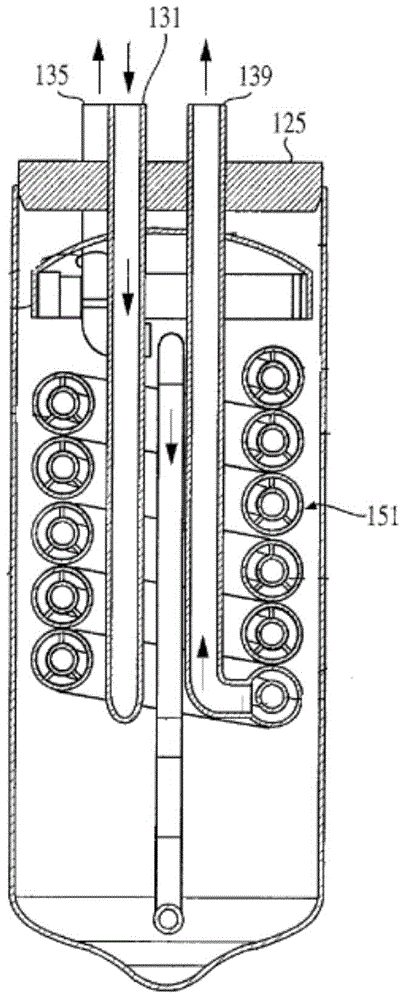
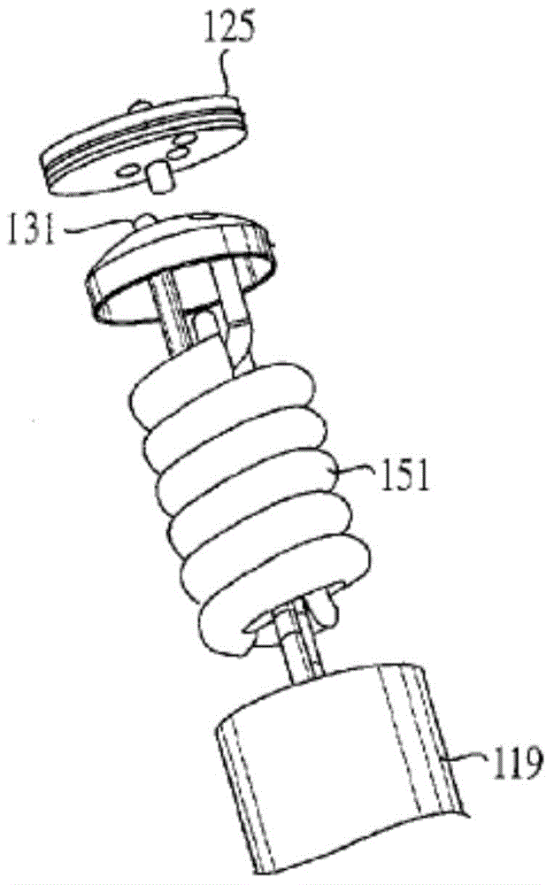
[0046] Please refer to Figure 5-9 , Figure 5 It is a structural schematic diagram of a specific embodiment of the gas-liquid separator provided by the present invention; Figure 6 for Figure 5 B-B direction sectional view; Figure 7 for Figure 6 Schematic diagram of the medium, high temperature and high pressure pipeline; Figure 8 for Figure 7 top view of Figure 9 for Figure 5 Schematic diagram of the connection between the middle head and the high-temperature and high-pressure pipelines and low-temperature and low-pressure pipelines located inside it.

[0047] The gas-liquid separator 10 is used in a carbon dioxide air conditioning system, that is, the refrigerant is carbon dioxide. The gas-liquid separa...


PUM


Abstract

The invention provides a carbon dioxide air-conditioning system and a gas-liquid separator thereof. The gas-liquid separator is provided with a low-temperature low-pressure pipeline and a high-temperature high-pressure pipeline, wherein the low-temperature low-pressure pipeline communicates with a compressor, and heat exchange is conducted between the high-temperature high-pressure pipeline and the low-temperature low-pressure pipeline. Both the low-temperature low-pressure pipeline and the high-temperature high-pressure pipeline are arranged independently. The high-temperature high-pressure pipeline is arranged spirally. The low-temperature low-pressure pipeline is inserted in a cylinder cavity formed by the spiral high-temperature high-pressure pipeline. As the high-temperature high-pressure pipeline and the low-temperature low-pressure pipeline of the gas-liquid separator are arranged independently, the gas-liquid separator can be technologically and easily obtained, the structure is simple, and the phenomenon of pipeline leakage is avoided; in addition, compared with the prior art, the space of the spiral cylinder cavity is utilized by the low-temperature low-pressure pipeline, so that under the conditions of the same spiral radius and the same spiral pipeline radius, the flow of a high-temperature high-pressure refrigerant is larger; and moreover, a low-temperature low-pressure refrigerant in the whole inner cavity can also participate in heat exchange, and thus a better heat exchange effect can be achieved.

Description

technical field [0001] The invention relates to the technical field of air conditioning, in particular to a carbon dioxide air conditioning system and a gas-liquid separator. Background technique [0002] In the automotive air conditioning system, the compressor only compresses the gaseous refrigerant. If a large amount of liquid refrigerant is sucked into the compressor, the compressor will be damaged and the system will be scrapped. Therefore, in the prior art, a gas-liquid separator is often installed between the evaporator and the compressor. [0003] The working principle of the gas-liquid separator is: the gas-liquid two-phase refrigerant coming out of the evaporator enters the gas-liquid separator. Under the action of gravity, the liquid refrigerant sinks and the gas refrigerant rises; The outlet end of the low-pressure pipeline is connected to the outside of the gas-liquid separator, and the inlet port is exposed to the inner cavity of the upper part of the gas-liqu...

Claims


Application Information

Patent Timeline
Patent Type & Authority Applications(China)
IPC IPC(8): F25B43/00F25B9/00
Inventor 汪立新蒋宗宝龚智勇
Owner ZHEJIANG SANHUA AUTOMOTIVE COMPONENTS CO LTD
Why Eureka
Try Eureka