Efficient spiral fin heat exchange device
A technology of spiral fin and heat exchange device, which is applied in the field of boiler flue gas heat exchange, can solve the problems of low heat exchange efficiency, the heat exchange efficiency of spiral fin tubes needs to be improved, etc., and achieve the effect of improving heat exchange efficiency.
- Summary
- Abstract
- Description
- Claims
- Application Information
AI Technical Summary
Problems solved by technology
Method used
Image

Examples
Embodiment 1
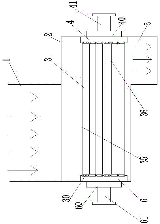
[0018] Embodiment 1, with reference to Figure 1-3 , a high-efficiency spiral fin heat exchange device, comprising: a closed shell 2, one side of the shell 2 is provided with an air inlet 21 connected to the boiler flue gas pipe 1;
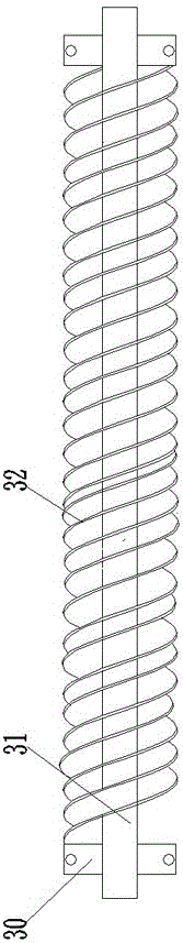
[0019] The spiral fin heat exchanger whose axial direction is perpendicular to the air inlet 21 includes the water inlet box 6 and the water outlet box 4 connected to the water inlet pipe 61 and the water outlet pipe 41 respectively, and the water inlet box 6 and the water inlet pipe 61 are connected to each other. A water inlet chamber 60 for buffering the flow velocity of water is also provided, and a water outlet chamber 40 is arranged between the water outlet pipe 41 and the water outlet box 4, and several spiral fins are arranged between the water inlet box 6 and the water outlet box 4. heat pipe 3, the two ends of the spiral fin heat exchange tube 3 are respectively connected to the water inlet tank 6 and the water outlet tank 4 through roll...
Embodiment 2
[0023] Embodiment 2, in the high-efficiency spiral fin heat exchange device described in Embodiment 1: the roller bearing 30 is a cylindrical roller bearing 30 .
Embodiment 3
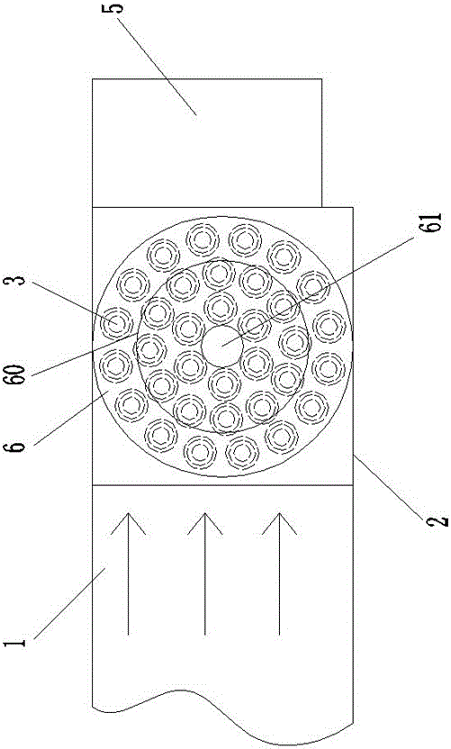
[0024] Embodiment 3, in the high-efficiency spiral fin heat exchange device described in Embodiment 1 or 2: the spiral fin heat exchange tubes 3 are evenly distributed on the sides of the water inlet tank 6 and the water outlet tank 4 .
[0025] The working principle of the present invention: Since the velocity of the boiler flue gas coming out of the boiler flue gas pipe can reach 12-15m / s, it has a large kinetic energy, and by setting the power heat exchange pipe section, the boiler flue gas impacts the power heat exchange pipe section to drive The spiral finned heat exchange tube rotates, which can reduce the kinetic energy of the boiler flue gas, reduce the velocity of the boiler flue gas, and increase the number of turns of the spiral finned heat exchange tube per unit time, so that the spiral fins can fully contact the boiler flue gas Heat exchange, increase the heat exchange area between the boiler flue gas and the spiral fins, and improve the heat exchange efficiency; a...
PUM
 Abstract
Description
Claims
Application Information
 - R&D
- Intellectual Property
- Life Sciences
- Materials
- Tech Scout
- Unparalleled Data Quality
- Higher Quality Content
- 60% Fewer Hallucinations
Browse by: Latest US Patents, China's latest patents, Technical Efficacy Thesaurus, Application Domain, Technology Topic, Popular Technical Reports.
© 2025 PatSnap. All rights reserved.Legal|Privacy policy|Modern Slavery Act Transparency Statement|Sitemap|About US| Contact US: help@patsnap.com