Optical cable automatic stripping and sampling device and optical capable sampling method

An automatic stripping and sampling device technology, applied in the field of optical cable manufacturing, can solve the problems of affecting the test accuracy, large damage to the sample performance, low test accuracy, etc., and achieve the effect of reducing the difficulty of sampling, reducing manual labor, and improving work quality

Active Publication Date: 2016-07-27
JIANGSU ETERN
View PDF8 Cites 3 Cited by
  • Summary
  • Abstract
  • Description
  • Claims
  • Application Information

AI Technical Summary

Problems solved by technology

[0003] At present, the sampling device used in the optical cable manufacturing plant needs to be completely cut by manual use of a knife. The performance of the sample is greatly damaged during cutting, and sampl

Method used


Image

  • Optical cable automatic stripping and sampling device and optical capable sampling method
  • Optical cable automatic stripping and sampling device and optical capable sampling method
  • Optical cable automatic stripping and sampling device and optical capable sampling method

Examples


Embodiment 1

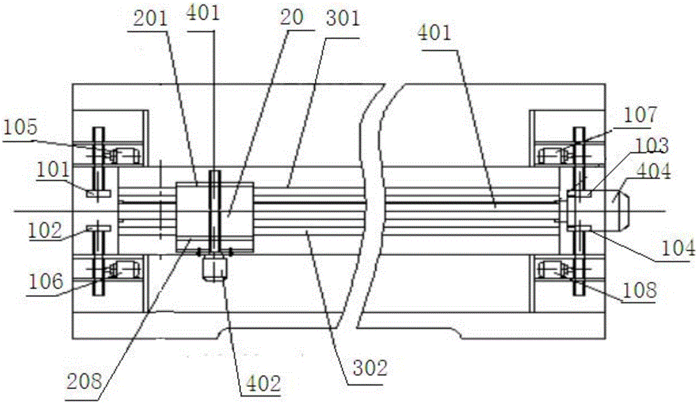
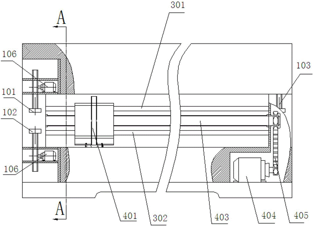
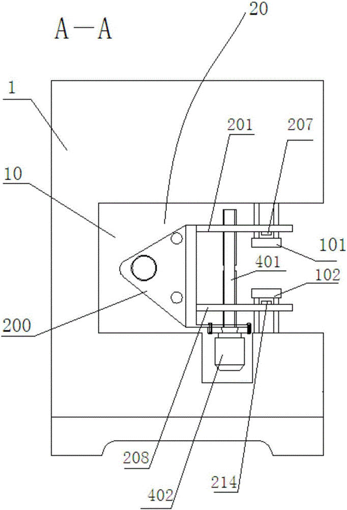
[0035] A kind of optical cable automatic stripping device is disclosed in embodiment 1, and this device is as Figure 1-6 As shown, it mainly includes a frame 1, on which a working space 10 for optical cable stripping and sampling is provided.

[0036]In the process of stripping and cutting the optical cable, the first step is to clamp and straighten the optical cable. The above-mentioned device realizes this function through the clamping parts that cooperate with each other. Specifically, the first clamping part is provided on the above-mentioned frame 1 101. The second clamping piece 102, the third clamping piece 103 and the fourth clamping piece 104, wherein the clamping ends of the first clamping piece 101 and the third clamping piece 103 face downward, and the second clamping piece 103 faces downward. The clamping ends of the clamping piece 102 and the fourth clamping piece 104 face upward, the above-mentioned first clamping piece 101 cooperates with the above-mentioned s...

Embodiment 2

[0050] Embodiment 2 discloses the sampling method of the optical cable automatic stripping sampling device in embodiment 1, which specifically includes the following steps:

[0051] Step 1. Place the optical cable to be sampled in the working space 10 on the frame, and the above-mentioned first clamping motor 105, second clamping motor 106, third clamping motor 107, and fourth clamping motor 108 respectively drive the above-mentioned The first clamping part 101 , the second clamping part 102 , the third clamping part 103 and the fourth clamping part 104 clamp the two ends of the optical cable to straighten the optical cable.

[0052] Step 2, the above-mentioned first motor 402 drives the above-mentioned first lead screw 401 to rotate, and the above-mentioned first lead screw 401 rotates to drive the above-mentioned second tool carrier 208 to move toward the above-mentioned first tool carrier 201, so that the above-mentioned first cutting assembly and the second cutting assembly...


PUM


Abstract

The invention discloses an optical cable automatic stripping and sampling device.The device is characterized in that four clamping motors drive four clamping part to achieve vertical transmission so as to clamp and loosen an optical cable, a cutting mechanism is used to fix the optical cable between grooved positioning wheels on two sides of cutters after the optical cable is clamped, 6 V-shaped pressing pieces which are vertically staggered are pressed on the optical cable, the two cutters directly facing the pressing pieces are pressed into the optical cable, and a power device for driving the cutting mechanism to move transversely is started so as to fast cut and sample the optical cable.The optical cable automatic stripping and sampling device has the advantages that manual work is replaced by the machine, work efficiency and work quality are increased greatly, manual labor is reduced, test accuracy is increased, and workers are prevented from being hurt by sampling; a key effect on the detecting efficiency is achieved, and sampling difficulty is lowered.

Description

technical field [0001] The invention relates to the technical field of optical cable manufacturing, in particular to a sampling device during an optical cable experiment, in particular to an optical cable automatic stripping sampling device and a sampling method. Background technique [0002] The stripping test of the optical cable and the performance test of the sheath of the optical cable are important items for the inspection of the optical cable before leaving the factory. The peeling strength of the optical cable and various properties of the sheath play a decisive role in the service life of the optical cable and the safety of the line. Therefore, the accuracy of detection and the quality of sampling have become difficult problems that must be solved. [0003] At present, the sampling device used in the optical cable manufacturing plant needs to be completely cut by manual use of a knife, which greatly damages the performance of the sample during cutting, and sampling ...

Claims


Application Information

Patent Timeline
IPC IPC(8): G01N1/08
CPCG01N1/08
Inventor 王少强沈锋陈钢陈晓红杨红蕾韦祖国姚子锋凌丹风夏桂军陈澍杨城
Owner JIANGSU ETERN
Why Eureka
Try Eureka