Photovoltaic system maximum power point tracing method

A maximum power tracking and maximum power point technology, applied in photovoltaic power generation, control/regulation systems, instruments, etc., can solve the problem of uncontrollable rate of voltage loop desaturation, insufficient power limit stability of full-load output power, and low power limit accuracy. higher question

Active Publication Date: 2016-07-27
厦门科华数能科技有限公司
View PDF5 Cites 4 Cited by
  • Summary
  • Abstract
  • Description
  • Claims
  • Application Information

AI Technical Summary

Problems solved by technology

[0003] The specific implementation method of adding a limiter at the rear stage of the voltage loop is that when the power limit occurs, the MPPT loop is in an invalid state, the voltage loop is in a saturated state, and the desaturation rate of the voltage loop is uncontrollable, and the re-execution of MPPT is false tracking. , or re-tracking and other reliability risks; the accuracy of power limit is not high, the power is easy to change suddenly, the output power at full load, and the stability of power limit is not enough, etc.

Method used


Image

  • Photovoltaic system maximum power point tracing method
  • Photovoltaic system maximum power point tracing method
  • Photovoltaic system maximum power point tracing method

Examples


Embodiment 1

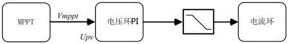
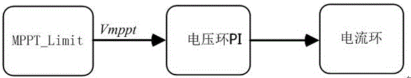
[0044] Photovoltaic system includes photovoltaic plate, DC / DC module (BOOST step-up unit), DC / AC inverter module, as attached image 3 , 4 As shown, the output value V of the MPPT_Limit loop with limited power mppt As a given value of the voltage loop, the voltage value of the photovoltaic plate U PV As the feedback value of the voltage loop, the output I of the voltage loop L_ref As the given value of the current loop, the output current value of DC / DC I boost As the feedback value of the current loop, the PWM signal of the output value of the current loop generates a driving signal through the PWM generator to act on the switching tube of the DC / DC module.

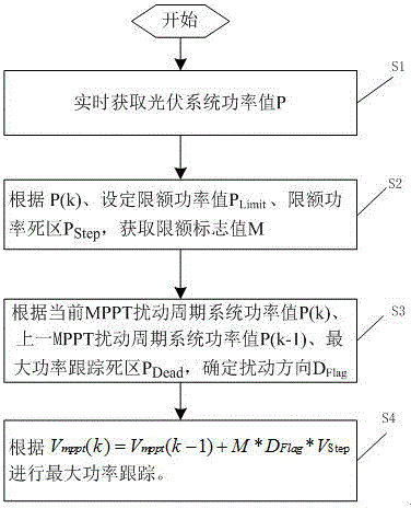
[0045] The maximum power point tracking method of the photovoltaic system comprises the following steps:

[0046] Step S1: Obtain the power value P of the photovoltaic system in real time, where the power value P of the photovoltaic system is the output voltage U of the photovoltaic module PV with output current I ...

Embodiment 2

[0067] The photovoltaic system includes photovoltaic plates and DC / AC inverter modules, as attached Figure 5 As shown, the output value V of the MPPT_Limit loop with limited power mppt As a given value of the voltage loop, the voltage value of the photovoltaic plate U PV As the feedback value of the voltage loop, the output I of the voltage loop L_ref As the given value of the current loop, the output current value of DC / AC I out As the feedback value of the current loop, the PWM signal of the output value of the current loop generates a driving signal through the PWM generator to act on the switching tube of the DC / AC module.

[0068] The maximum power point tracking method of the photovoltaic system comprises the following steps:

[0069] Step S1: Obtain the power value P of the photovoltaic system in real time, where the power value P of the photovoltaic system is the output voltage U of DC / AC out with output current I out The product of P=U out *I out ;

[0070]St...


PUM


Abstract

The invention provides a photovoltaic system maximum power point tracing method. The method comprises the steps that 1, the power value P of a photovoltaic system is obtained in real time; 2, a limit marking value M is obtained according to the current MPPT disturbance period system power value P(k), the set limit power value PLimit and the limit power dead zone PStep; 3, the disturbance direction DFlag is determined according to the current MPPT disturbance period system power value P(k), the previous MPPT disturbance period system power value P(k-1) and the maximum power tracking dead zone PDead; 4, according to the formula: Vmmpt(k)=Vmppt(k-1)+M*DFlag*VStep, the maximum power disturbance voltage Vmppt (k) is obtained for maximum power tracking. By the adoption of the technical scheme, the photovoltaic system maximum power point tracing method has the advantages that full load and limiting output power of a photovoltaic inverter are smooth; the full-load power and limit power of the photovoltaic system are accurate, and the output power is stable; bus voltage is more stable, and a system loop is more reliable.

Description

technical field [0001] The invention relates to the field of photovoltaic power generation, in particular to a method for tracking the maximum power point of a photovoltaic system. Background technique [0002] attached figure 1 The MPPT algorithm of the traditional grid-connected inverter is generally controlled by the three-loop control operation of MPPT, voltage loop and current loop. When the input power exceeds the operating power of the equipment, it is common practice to add a limiter after the voltage loop. [0003] The specific implementation method of adding a limiter at the rear stage of the voltage loop is that when the power limit occurs, the MPPT loop is in an invalid state, the voltage loop is in a saturated state, and the desaturation rate of the voltage loop is uncontrollable, and the re-execution of MPPT is false tracking. , or re-tracking and other reliability risks; the accuracy of power limit is not high, the power is easy to change suddenly, the full l...

Claims


Application Information

Patent Timeline
Patent Type & Authority Applications(China)
IPC IPC(8): G05F1/67
CPCG05F1/67Y02E10/56
Inventor 黄伟平苏宁焕张惠珍张发展
Owner 厦门科华数能科技有限公司
Why Eureka
Try Eureka