An ultrasonic inspection device for nuclear reactor pressure vessel joint intersection surface
A pressure vessel, ultrasonic inspection technology, used in nuclear reactor monitoring, reactors, nuclear engineering, etc., can solve the problem of inability to use a fixed motion trajectory scanning method, and achieve the effect of reduced external size, constant size, and easy installation
- Summary
- Abstract
- Description
- Claims
- Application Information
AI Technical Summary
Problems solved by technology
Method used
Image
Examples
Embodiment 1
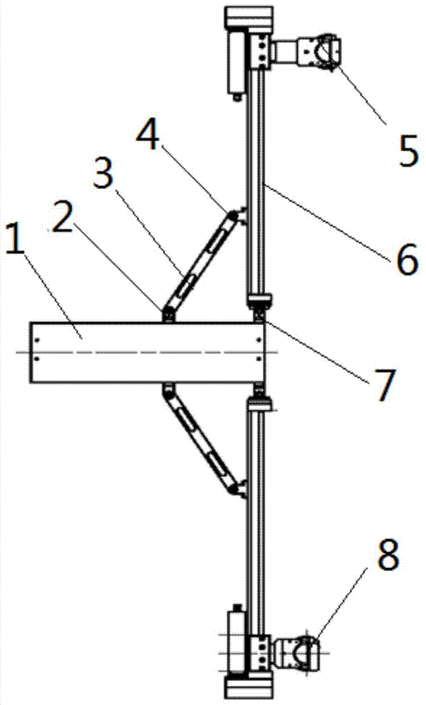
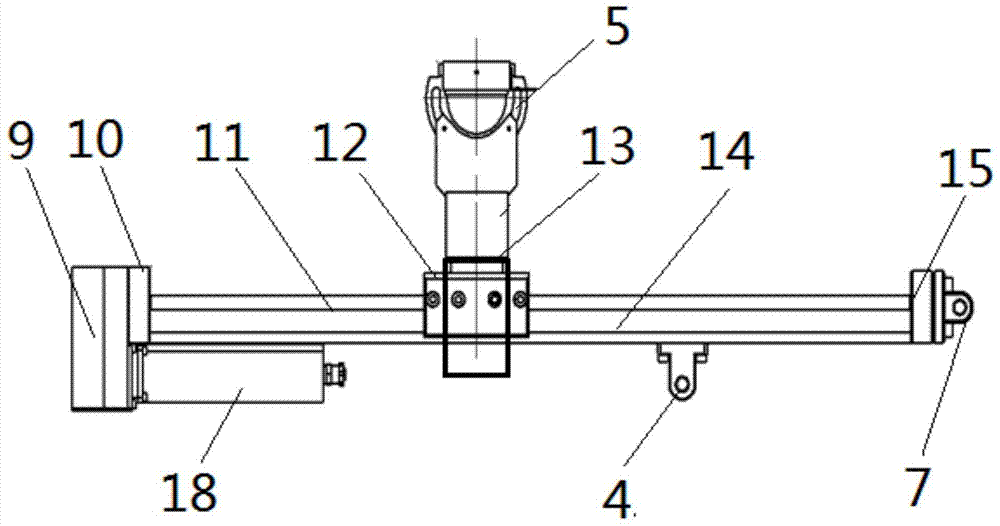
[0019] Such as figure 1 , figure 2 As shown, an ultrasonic inspection device for the junction surface of nuclear reactor pressure vessel includes a driving cylinder 1, a connecting rod 3, a retractable probe holder 5, a scanning arm 6 and a fixed probe holder 8, wherein, The lower end of the driving cylinder part 1 is movably connected with the ends of the two symmetrically distributed scanning arms 6 through the hinge C7, the driving part in the middle part of the driving cylinder part 1 is movably connected with one end of the connecting rod 3 through the hinge A2, and the other end of the connecting rod 3 is through the hinge B4 It is movably connected with the scanning arm 6; the drive cylinder 1 drives the two symmetrically distributed scanning arms 6 to shrink or expand through the connecting rod 3; Box 9, wherein a motor 18 and a reduction box 9 are fixedly installed on the end of the guide rail 14 away from the hinge C7, the lead screw 11 is installed on the guide ra...
Embodiment 2
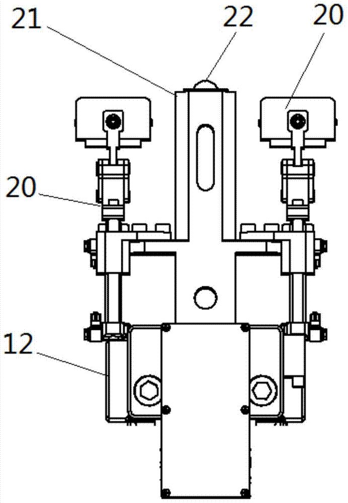
[0022] Such as image 3 As shown, an ultrasonic inspection device for a nuclear reactor pressure vessel joint intersection surface includes a driving cylinder 1, a connecting rod 3, a scanning arm 6, and a probe holder with a support rod structure, wherein the lower end of the driving cylinder 1 passes through the hinge C7 is movably connected with the ends of two symmetrically distributed scanning arms 6, the driving part in the middle of the driving cylinder part 1 is movably connected with one end of the connecting rod 3 through the hinge A2, and the other end of the connecting rod 3 is movably connected with the scanning arm 6 through the hinge B4 ; The drive cylinder 1 drives two symmetrically distributed scanning arms 6 to contract or expand through the connecting rod 3; 14 One end away from the hinge C7 is fixedly installed with a motor 18 and a reduction box 9. The screw 11 is installed on the guide rail 14 in parallel with the bearing seat B15 through the bearing seat...
PUM
 Abstract
Description
Claims
Application Information
 - R&D
- Intellectual Property
- Life Sciences
- Materials
- Tech Scout
- Unparalleled Data Quality
- Higher Quality Content
- 60% Fewer Hallucinations
Browse by: Latest US Patents, China's latest patents, Technical Efficacy Thesaurus, Application Domain, Technology Topic, Popular Technical Reports.
© 2025 PatSnap. All rights reserved.Legal|Privacy policy|Modern Slavery Act Transparency Statement|Sitemap|About US| Contact US: help@patsnap.com


