Inductive coupling plasma reactor

A plasma reactor, inductive coupling technology, applied in circuits, discharge tubes, electrical components, etc., can solve problems such as uneven plasma concentration distribution

Active Publication Date: 2016-07-27
ADVANCED MICRO FAB EQUIP INC CHINA
View PDF9 Cites 2 Cited by
  • Summary
  • Abstract
  • Description
  • Claims
  • Application Information

AI Technical Summary

Problems solved by technology

[0003] Therefore, the inductively coupled plasma processor needs to be further improved to solve the problem of uneven distribution of plasma concentration naturally existing in radially arranged iron cores.

Method used


Image

  • Inductive coupling plasma reactor
  • Inductive coupling plasma reactor
  • Inductive coupling plasma reactor

Examples


Embodiment Construction

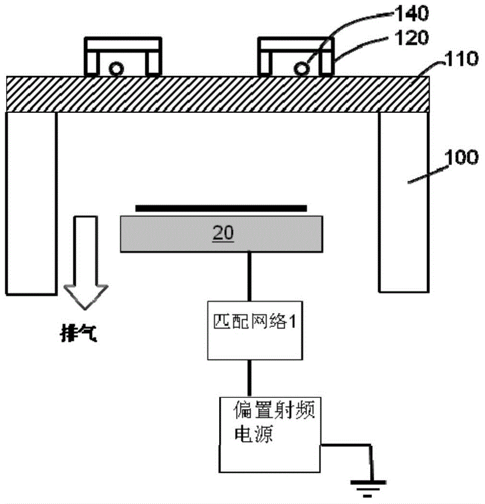
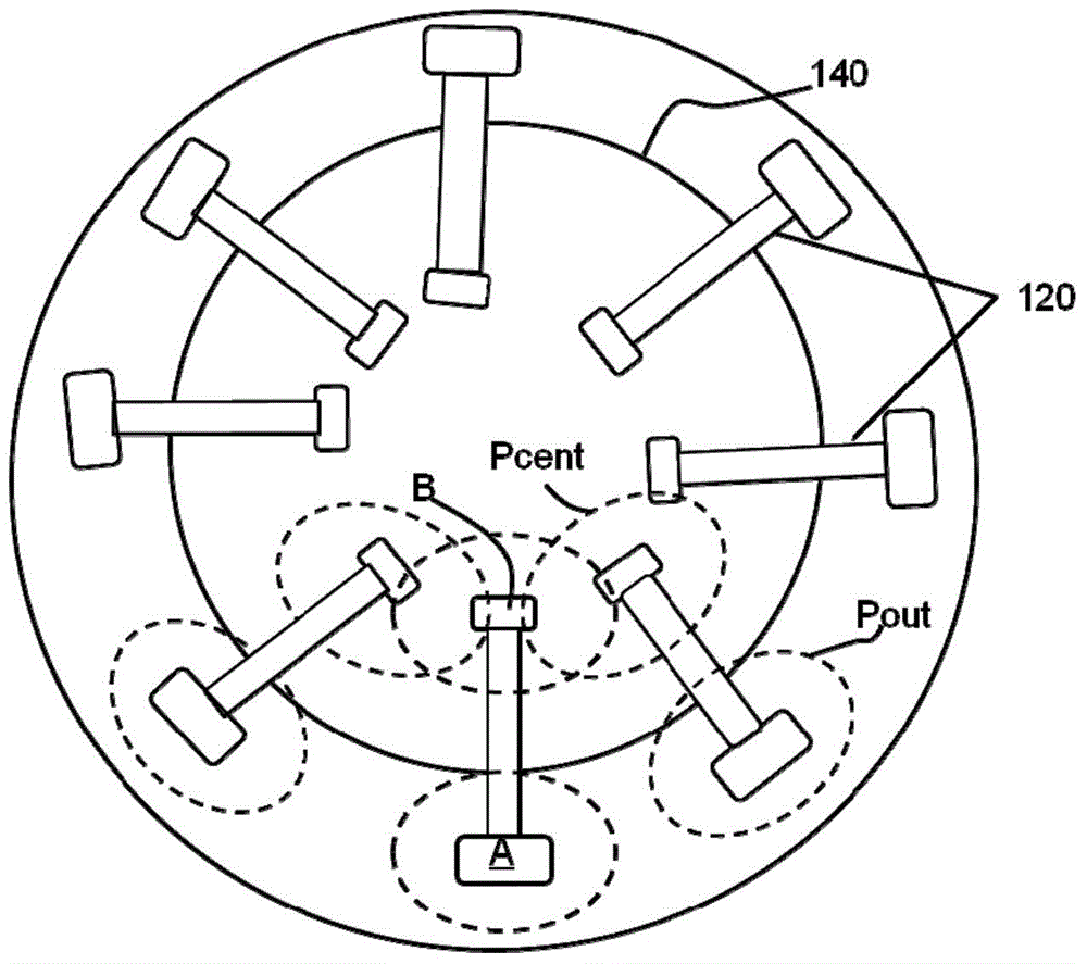
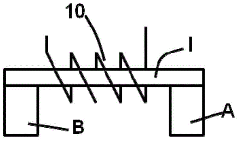
[0017] The present invention aims to solve the problem of uneven distribution of plasma concentration in the central area and the peripheral area in the inductively coupled plasma processing device, and proposes such as figure 2 The iron core and coil structure of the first embodiment of the present invention is shown, wherein the iron core includes a horizontally extending portion I, and also includes a first downwardly extending portion A, a second downwardly extending portion B1 and a third downwardly extending portion B2, An induction coil is wound on the horizontal extension I11 between the first and second downward extensions.

[0018] The magnetic field line circuit such as figure 2 As shown by the dotted line in the middle, the first loop passes along A, I11, B1 and finally returns to A through the air, and the second loop passes through A, I11, I12, B2 and finally returns to A through the air between the lower end of B2 and A.

[0019] Wherein, end A is located at ...


PUM


Abstract

The invention discloses an inductive coupling plasma rector. The inductive coupling plasma rector comprises a reaction chamber; an insulation material window disposed in the top of the reaction chamber; and a pedestal, which is used for fixing a substrate, and is disposed in the lower part of the reaction chamber. The upper part of the insulation material window comprises an iron core assembly. The inductive coupling plasma rector is characterized in that the iron core assembly comprises a horizontal extension part and a plurality of downward extension parts disposed on the lower part; by designing the magnetic resistance between every downward extension part and the horizontal extension part, the magnetic resistance value passing through every downward extension part can be gradually increased from the center of the insulation material window to the external periphery, and the plasma concentration in the corresponding lower reaction chamber can be increased gradually. The plasma concentration reaching the surface of the substrate after the diffusion can be more uniform.

Description

technical field [0001] The invention relates to the technical field of semiconductor manufacturing, in particular to an iron core structure of an inductively coupled plasma reactor. Background technique [0002] Such as Figure 1a As shown, the conventional inductively coupled plasma processing device includes a reaction chamber 100, the reaction chamber includes a base 20, and the base includes a lower electrode. An electrostatic chuck is included above the susceptor, and the substrate to be processed is set on the electrostatic chuck. A bias RF power supply 35 with a lower frequency (such as 2Mhz-400Khz) is connected to the lower electrode in the base 20 through a matcher. Exhaust passages are included around the outside of the susceptor to maintain a low air pressure within the plasma processing apparatus. The top of the reaction chamber also includes a window 110 of insulating material, above the window of insulating material includes an inductance coil 140, and the in...

Claims


Application Information

Patent Timeline
Patent Type & Authority Applications(China)
IPC IPC(8): H01J37/32
Inventor 张辉倪图强
Owner ADVANCED MICRO FAB EQUIP INC CHINA
Why Eureka
Try Eureka