Micro/nano-satellite reaction flywheel control method based on linear Hall

A reaction flywheel and linear Hall technology, applied in control systems, control generators, vector control systems, etc., can solve the problems of high cost, heavy weight, and not meeting the weight and cost requirements of micro-nano satellites, and reduce lead wires number, high-efficiency drives, and the effect of reducing storage and computing resource requirements

Active Publication Date: 2016-07-27
SHANGHAI XINYUE METER FACTORY
View PDF6 Cites 10 Cited by
  • Summary
  • Abstract
  • Description
  • Claims
  • Application Information

AI Technical Summary

Problems solved by technology

[0004] In the prior art, for the control of the flywheel, photoelectric encoders and switch Hall sensors are used to obtain information such as the position and speed of the flywheel rotor, which is heavy and costly, and does not meet the weight and cost requirements of micro-nano satellites

Method used


Image

  • Micro/nano-satellite reaction flywheel control method based on linear Hall
  • Micro/nano-satellite reaction flywheel control method based on linear Hall
  • Micro/nano-satellite reaction flywheel control method based on linear Hall

Examples


Embodiment Construction

[0034] The following will combine Figure 1 to Figure 7 The linear Hall-based micro-nano-satellite reaction flywheel control method of the present invention is further described in detail.

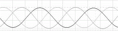
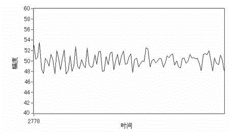
[0035] The invention uses a linear Hall sensor instead of a photoelectric encoder and a switch Hall sensor, and uses the output signal of the linear Hall sensor to obtain information such as the position and speed of the flywheel rotor.

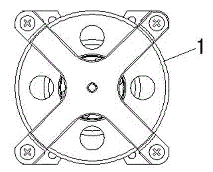
[0036] figure 1 Shown is a schematic diagram of the structure of the micro-nano-satellite reaction flywheel in a preferred embodiment of the present invention, figure 1 Shown is a schematic structural view of the stator of the reaction flywheel motor (hereinafter referred to as the stator) for micro-nano-satellites in a preferred embodiment of the present invention. combine figure 1 and figure 2 , in the present embodiment, micro-nano-satellite reaction flywheel adopts DC brushless motor, and this stator is 14 poles, 12 groove sub-slot windings, and ...


PUM


Abstract

The invention discloses a micro / nano-satellite reaction flywheel control method based on linear Hall. The method comprises the steps of (1) acquiring an electrical angle theta and an angular velocity omega at a rotor position of a reaction flywheel motor from output signals of three linear Hall sensors distributed uniformly along the same circumference; and (2) obtaining a reference signal of a three-phase current control instruction for a stator of the reaction flywheel motor from the output signals of the three linear Hall sensors, thus controlling a reaction flywheel. The micro / nano-satellite reaction flywheel control method based on linear Hall is low in cost, stable in control effect and high in driving efficiency.

Description

technical field [0001] The invention relates to a reaction flywheel, in particular to a linear Hall-based micro-nano satellite reaction flywheel control method. Background technique [0002] In the past two decades, technologies such as microelectronics, micromechanics, computers, communications, and energy have made rapid progress. By adopting these high technologies, the weight and volume of satellites with the same function have been greatly reduced, and micro-nano satellites with more comprehensive functions have emerged. Satellites and even pico-satellites. Micro-nano satellites have many incomparable advantages over large satellites, such as small size, light weight, low development and launch costs, and short development cycles. Due to the adoption of new design ideas, new technologies, and new management modes of manufacturing and production, micro-nano satellites have become the most active, challenging and promising space technology field, and are also an import...

Claims


Application Information

Patent Timeline
Patent Type & Authority Applications(China)
IPC IPC(8): H02P21/00
Inventor 嵩甲晨李结冻侯建文李延宝刘珊珊刘正全毕振瀚
Owner SHANGHAI XINYUE METER FACTORY
Why Eureka
Try Eureka