An adjustable integrated power supply device

A power supply device and adjustable technology, applied in gardening tools/equipment, botanical equipment and methods, electrical components, etc., can solve the problems of inconvenient movement of cultivated plants, high power consumption, easy damage, etc., to achieve the integration of convenience management, reduce power consumption, and facilitate adjustment

Active Publication Date: 2019-02-12
STATE GRID SHANDONG ELECTRIC POWER CO LONGKOU POWER SUPPLY CO
View PDF9 Cites 0 Cited by
  • Summary
  • Abstract
  • Description
  • Claims
  • Application Information

AI Technical Summary

Problems solved by technology

[0002] Because the power equipment is usually turned on for a long time in the artificial garden, the power consumption is relatively large. At the same time, during use, because the cultivated plants cannot be moved conveniently, it is easy to be damaged in bad weather

Method used


Image

  • An adjustable integrated power supply device

Examples


Embodiment 1

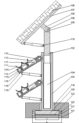
[0024] Such as figure 1 As shown, an adjustable integrated power supply device includes a movable base 101 and a lifting rod 102 arranged above the movable base, a support 103 is arranged below the lifting rod, and the middle part of the support A cavity is provided, the lower end of the lifting rod is plugged into the middle of the support, and a lifting device is arranged below the lifting rod;

[0025] A photovoltaic panel 106 is arranged on the top of the lifting rod, a photovoltaic panel bracket 107 is arranged on the lower end surface of the photovoltaic panel, and a flange structure 105 is arranged under the middle part of the photovoltaic panel bracket. A groove 108 is provided on the top of the rod, and the flange structure is inserted into the middle of the groove, and the flange structure is rotatably connected to the lifting rod through a rotating shaft 109 passing through the groove;

[0026] A plant bracket 110 is arranged outside one side of the support, and th...

Embodiment 2

[0030] In this embodiment, on the basis of Embodiment 1, in order to adjust the angle of the plant bracket conveniently, preferably, one end of the plant bracket is hinged on the side wall of the support.

[0031] Further preferably, in order to facilitate control, a hydraulic pushing device 118 is provided on the side wall of the support, one end of the hydraulic pushing device is hinged on the side wall of the support, and the other end of the hydraulic pushing device It is hinged on the lower end surface of the end of the plant bracket away from the support. The angle adjustment is realized by pushing the plant bracket to rotate around its hinged end through the hydraulic pushing device.

[0032] In order to facilitate the adjustment of the angle of the photovoltaic panel, in this embodiment, preferably, a hydraulic pushing device 118 is provided on the side wall of the lifting rod, and one end of the hydraulic pushing device is hinged on the side wall of the lifting rod T...

Embodiment 3

[0034] In this embodiment, on the basis of Embodiment 1 or 2, in order to facilitate the installation of the support, preferably, an installation groove 119 is provided on the movable base, and the lower end of the support is located inside the installation groove.

[0035] In this embodiment, in order to make the support more stable, preferably, the installation groove is an inverted T-shaped groove, and a positioning plate 120 is provided under the support, and the positioning plate is located on the mounting surface. trough bottom.

[0036] In order to avoid damage to the support when subjected to a force in the horizontal direction, in this embodiment, the width l of the positioning plate is smaller than the width L of the bottom of the installation groove. The positioning plate can move in the horizontal direction at the bottom of the installation groove, so as to buffer the force and prevent the force from directly affecting the support.

[0037] In order to reduce the ...


PUM


Abstract

The invention discloses an adjustable integrated power supply device which comprises a moveable base and a lifting rod, wherein the lifting rod is arranged above the moveable base; a supporting base is arranged under the lifting rod; a chamber is arranged in the middle of the supporting base; the lower end of the lifting rod is inserted into the middle part of the supporting base; a lifting device is arranged under the lifting rod; a photovoltaic plate is arranged on the top of the lifting rod; a photovoltaic plate bracket is arranged on the lower end face of the photovoltaic plate; a flange structure is arranged under the middle part of the photovoltaic plate bracket; a groove is formed in the top of the lifting rod; the flange structure is grafted in the middle part of the groove; the flange structure is in rotating connection with the lifting rod by penetrating through a rotating shaft of the groove. According to the invention, the photovoltaic plate is adopted for realizing power supply of the garden, the energy consumption can be reduced and the resource use efficiency is improved.

Description

technical field [0001] The invention relates to an adjustable integrated power supply device. Background technique [0002] Because the power equipment is usually turned on for a long time in the artificial garden, the power consumption is relatively large. At the same time, during use, because the cultivated plants cannot be moved conveniently, it is easy to be damaged when encountering bad weather. Contents of the invention [0003] The purpose of the present invention is to provide an adjustable integrated power supply device, which can improve the problems existing in the prior art, realize garden power supply by using photovoltaic panels, reduce energy consumption, and improve resource utilization efficiency. [0004] The present invention is realized through the following technical solutions: [0005] An adjustable integrated power supply device, comprising a movable base and a lifting rod arranged above the movable base, a support is arranged below the lifting rod,...

Claims


Application Information

Patent Timeline
Patent Type & Authority Patents(China)
IPC IPC(8): H02S20/30A01G9/02
CPCA01G7/04A01G9/02H02S20/30Y02E10/50
Inventor 高菁张玉华曲珈萱王元春贾铭坤姜婷婷李如马健于本东
Owner STATE GRID SHANDONG ELECTRIC POWER CO LONGKOU POWER SUPPLY CO
Why Eureka
Try Eureka