Cookware

A technology for cooking utensils and pot lids, which is applied in the field of kitchen utensils. It can solve the problems that the gas in the pot lid is not easy to discharge, the difficulty of closing the lid is increased, and the action of closing the lid is hindered, so as to avoid the phenomenon of sucking pot, reduce user complaints, and improve safety. Effect

Active Publication Date: 2016-08-03
FOSHAN SHUNDE MIDEA ELECTRICAL HEATING APPLIANCES MFG CO LTD
View PDF5 Cites 6 Cited by
  • Summary
  • Abstract
  • Description
  • Claims
  • Application Information

AI Technical Summary

Problems solved by technology

[0002] After the existing electric pressure cooker is heated, its sealing ring is heated and expands, thereby realizing the seal between the inner pot and the pot cover, and in a relatively short period of time after the heating is stopped, the sealing ring is still in an expanded state. Therefore, if there is no leak Press the weak part to create a gap between the sealing ring and the inner pot or the lid, then within a short period of time after stopping heating, the sealing ring will still suck the inner pot because the inside of the pot is still disconnected from the outside. Therefore, when opening the lid within a short period of time after stopping heating, the sealing ring still has a certain suction force on the inner pot, so it is very easy to suck up the inner pot, that is, the so-called suction pot phenomenon is very easy to occur, and then the inner pot is under the force of gravity. Very vulnerable to breakage when dropped
At the same time, in the process of closing the lid of the electric pressure cooker, the gas between the lid and the sealing ring needs to be discharged through the extrusion of the inner pot and the sealing ring. When the lid is covered, the gas in the lid will not be easily discharged because the electric pressure cooker does not leak, thus hindering the lid closing action and increasing the difficulty of closing the lid

Method used


Image

  • Cookware
  • Cookware
  • Cookware

Examples


Embodiment Construction

[0050] In order to understand the above-mentioned purpose, features and advantages of the present invention more clearly, the present invention will be further described in detail below in conjunction with the accompanying drawings and specific embodiments. It should be noted that, in the case of no conflict, the embodiments of the present application and the features in the embodiments can be combined with each other.

[0051] In the following description, many specific details are set forth in order to fully understand the present invention. However, the present invention can also be implemented in other ways different from those described here. Therefore, the protection scope of the present invention is not limited by the specific details disclosed below. EXAMPLE LIMITATIONS.

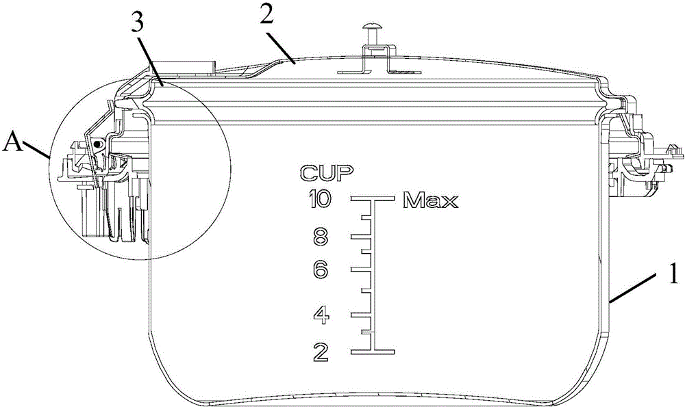
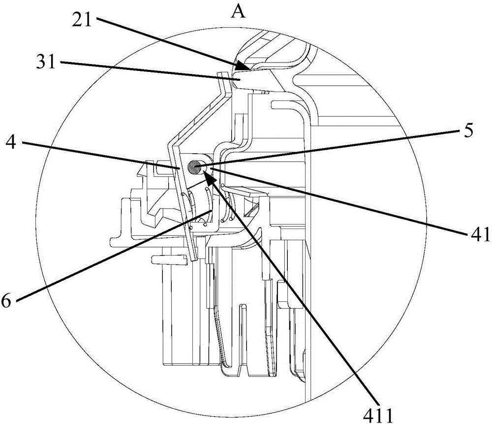
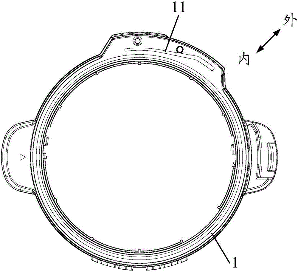
[0052] Refer below Figure 1 to Figure 7 Cooking appliances according to some embodiments of the invention are described.

[0053] Such as Figure 1 to Figure 7 As shown, the embodiment of the fir...


PUM


Abstract

The invention provides cookware. The cookware comprises a pot, a pot cover and a sealing ring, wherein the pot cover is rotatably arranged on the pot between the covering position and the uncovering position, a guiding groove extending from the covering position to the uncovering position is formed in the pot, and when the guiding groove extends from the covering position to the uncovering position, the guiding groove extends from the inner edge of the pot to the outer edge of the pot; the pot cover is provided with a through hole and a push rod assembled on the pot cover; the sealing ring is installed in the pot cover and comprises a ring body and a positioning protrusion which is arranged on the ring body and penetrates through the through hole; when the pot cover is rotated to the uncovering position from the covering position, the push rod squeezes the positioning protrusion under the guiding of the guiding groove to enable a gap to be formed between the sealing ring and the through hole. According to the technical scheme, during uncovering, compressional deformation of the sealing ring can be caused and the gap can be formed between the sealing ring and the through hole under the action of the push rod and the guiding groove, so that the interior of the pot can be communicated with outside atmosphere, and then the phenomenon that an inner pot body is lift under the adsorption of the sealing ring and then falls down during uncovering can be avoided, in other words, the pot suction phenomenon can be avoided.

Description

technical field [0001] The invention relates to the field of kitchen utensils, in particular to a cooking utensil. Background technique [0002] After the existing electric pressure cooker is heated, its sealing ring is heated and expands, thereby realizing the seal between the inner pot and the pot cover, and in a relatively short period of time after the heating is stopped, the sealing ring is still in an expanded state. Therefore, if there is no leak Press the weak part to create a gap between the sealing ring and the inner pot or the lid, then within a short period of time after stopping heating, the sealing ring will still suck the inner pot because the inside of the pot is still disconnected from the outside. Therefore, when opening the lid within a short period of time after stopping heating, the sealing ring still has a certain suction force on the inner pot, so it is very easy to suck up the inner pot, that is, the so-called suction pot phenomenon is very easy to oc...

Claims


Application Information

Patent Timeline
Patent Type & Authority Applications(China)
IPC IPC(8): A47J27/08A47J27/09
CPCA47J27/08A47J27/0804A47J27/09
Inventor 蔡位明
Owner FOSHAN SHUNDE MIDEA ELECTRICAL HEATING APPLIANCES MFG CO LTD
Why Eureka
Try Eureka