Unfolding device of steel ball sorting machine

A technology of sorting machines and steel balls, which is applied in sorting and other directions, can solve the problems of not being able to guarantee complete coverage of the steel ball surface, low detection efficiency, and short service life, so as to achieve accurate steel ball sorting, reduce motor loss, and prolong The effect of service life

Active Publication Date: 2016-08-03
NINGBO BAIJIABAI MEASUREMENT & CONTROL EQUIP
View PDF8 Cites 3 Cited by
  • Summary
  • Abstract
  • Description
  • Claims
  • Application Information

AI Technical Summary

Problems solved by technology

[0003] For the steel ball unfolding device of the steel ball sorting machine based on machine vision at present, refer to a kind of steel ball sorting device and method based on machine vision disclosed in Chinese patent (notification number CN102658266B), which adopts the detection cavity in the feed plate to carry The steel ball rotates at a certain speed, and the expansion of the steel ball depends on the periodic rotation and intermittent translation of the bottom friction disc to make the steel ball eccentrically move, so as to achieve the effect of unfolding the surface of the steel ball to be tested. The combination of the feed disc and the friction disc is adopted. The unfolding device needs to drive the steel balls in the detection chamber to roll and unfold when the feed plate rotates, that is, the feed plate has both the functions of feeding steel balls and unfolding steel balls. In order to ensure that the steel balls can roll smoothly, the distance between the detection chamber and the steel balls There must be a certain gap between them, which causes the steel ball to roll randomly to a certain extent, so the image obtained by this method is random and cannot guarantee complete coverage of the steel ball surface
Another problem is that the feed plate can only feed one steel ball per rotation, the detection efficiency is low, and the loss of the motor is large, and the service life is short

Method used


Image

  • Unfolding device of steel ball sorting machine
  • Unfolding device of steel ball sorting machine
  • Unfolding device of steel ball sorting machine

Examples


Embodiment Construction

[0018] The following descriptions are only preferred embodiments of the present invention, and therefore do not limit the protection scope of the present invention.

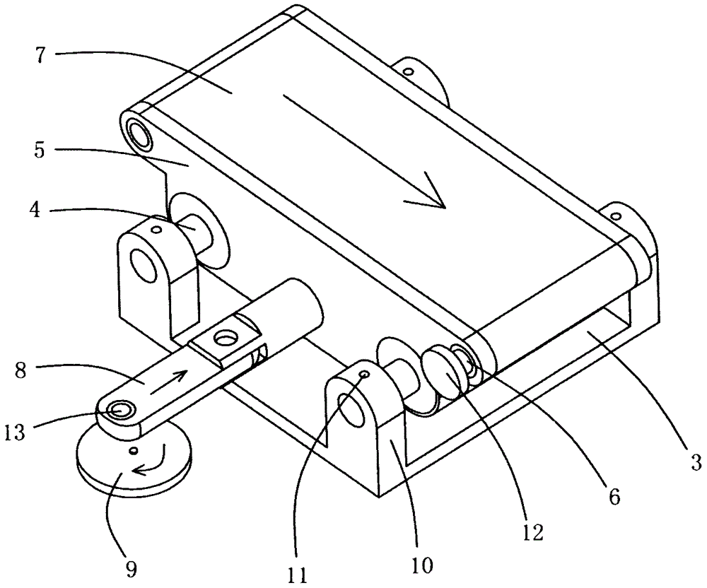
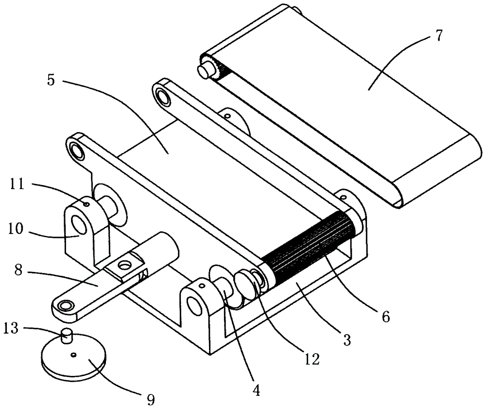
[0019] see Figure 1-Figure 3 , a steel ball sorting machine deployment device, including a feed tray 1, the feed tray 1 is provided with a number of detection chambers 2 for carrying steel balls, and also includes a mounting seat 3, the mounting seat 3 is provided with a slide rail 4, the slide The rail 4 is provided with a sliding seat 5, and the sliding seat 5 is provided with a friction belt 7 driven by the roller shaft 6. The friction belt 7 is located under the feed plate 1 and is used to drive the steel ball to roll in the detection chamber 2; it also includes a connecting rod 8. One end of the connecting rod 8 is hinged with the sliding seat 5, and the other end of the connecting rod 8 is eccentrically connected with the runner 9, and the runner 9 drives the sliding seat 5 to slide along the slide rail 4 ...


PUM


Abstract

The invention discloses an unfolding device of a steel ball sorting machine. The unfolding device comprises a feeding disc; and the feeding disc is provided with multiple detecting cavities for bearing steel balls. The unfolding device further comprises a mounting base; a slide rail is arranged on the mounting base; a slide base is arranged on the slide rail; and a friction belt driven by a roller shaft is arranged on the slide base, is positioned below the feeding disc, and is used for driving the steel balls to roll in the detecting cavities. The unfolding device further comprises a connecting rod; one end of the connecting rod is hinged to the slide base, and the other end of the connecting rod is eccentrically connected with a rotating wheel; the rotating wheel drives the slide base to slide along the slide rail through the connecting rod; and the conveying direction of the friction belt is orthogonal to the sliding direction of the slide base. The unfolding device adopts the rolling friction belt to drive the steel balls in the detecting cavities of the feeding disc to roll and unfold, can guarantee total unfolding of the steel balls, can guarantee total coverage of the surfaces of the steel balls by obtained images, is more precise in sorting of the steel balls, can feed the steel balls in batches through the feeding disc, improves the detecting efficiency, reduces the motor loss, and prolongs the motor service life.

Description

technical field [0001] The invention relates to the technical field of steel ball sorting equipment based on machine vision, in particular to a steel ball sorting machine deployment device. Background technique [0002] Machine vision is to use machines instead of human eyes for measurement and judgment. Machine vision technology refers to converting the captured target into an image signal through machine vision products (ie, image capture device, which is divided into CMOS and CCD) and transmitting it to a dedicated image. The processing system converts the information into digital signals according to pixel distribution, brightness, color and other information; the image system performs various calculations on these signals to extract the characteristics of the target, and then controls the on-site equipment actions according to the results of the discrimination. The surface defect detection of bearing steel balls based on machine vision technology is currently a hot rese...

Claims


Application Information

Patent Timeline
Patent Type & Authority Applications(China)
IPC IPC(8): B07C5/02
CPCB07C5/02
Inventor 李林灿李方
Owner NINGBO BAIJIABAI MEASUREMENT & CONTROL EQUIP
Why Eureka
Try Eureka