
Composite hole machining cutter capable of being spliced and combined

A hole machining and compound technology, applied in the direction of tools, manufacturing tools, metal processing equipment for lathes, etc., can solve the problems that the utilization rate of tools cannot be maximized, it is not suitable to promote the use of combined tools, and the reliability is not enough. To achieve the effect of simple structure, reduced cycle, and improved utilization

Inactive Publication Date: 2016-08-03
SHANGHAI UNIV
View PDF7 Cites 1 Cited by
  • Summary
  • Abstract
  • Description
  • Claims
  • Application Information

AI Technical Summary

Problems solved by technology

[0003] The damage of a compound tool is often a part of the tool is damaged, but part of the damage leads to the scrapping of the entire knife. When the individual blades of the compound tool are scrapped, other blades are still in good working condition, but the compound tool is still treated as scrap. Therefore, the utilization rate of the tool cannot be maximized
[0004] Most of the existing spliced ​​compound tools are connected by screws, and the cutting force is all borne by the screws. In some heavy-duty cutting, the reliability is not enough. The positioning of the tool is also a problem by relying on the screws alone.
The fixed knob and clamping bolt are used to fix the two spliced ​​cutter bodies. This structure makes the cutter relatively long and large, and it is not suitable to promote the use of combined cutters.

Method used


Image

  • Composite hole machining cutter capable of being spliced and combined
  • Composite hole machining cutter capable of being spliced and combined
  • Composite hole machining cutter capable of being spliced and combined

Examples


Embodiment Construction

[0018] The preferred embodiments of the present invention are given below in conjunction with the accompanying drawings to describe the technical solution of the present invention in detail.

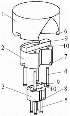
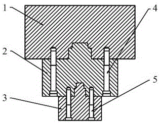
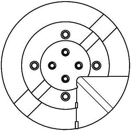
[0019] Such as Figure 1 to Figure 8 As shown, the present invention can be spliced ​​and combined compound hole machining tool comprising a first cutter body 1, a second cutter body 2, a third cutter body 3, an upper fastening screw 4, a lower fastening screw 5, an outer blade 6, an auxiliary Blade 7, inner blade 8, tapered platform 9, square platform 10, edge protection 11, tapered groove 12, square groove 13, threaded hole 14, stepped hole 15, the first cutter body 1 is fixed on the second cutter body 2 Above, the second cutter body 2 is fixed above the third cutter body 3, the upper fastening screw 4 is located on the second cutter body 2, the lower fastening screw 5 is located on the third cutter body 3, and the outer blade 6 is installed on the first cutter body Body 1 side, auxil...


PUM

PropertyMeasurementUnit
Taperaaaaaaaaaa

Abstract

The invention discloses a composite hole machining cutter capable of being spliced and combined. The composite hole machining cutter capable of being spliced and combined comprises a first cutter body and the like; the first cutter body is fixed above a second cutter body which is fixed above a third cutter body; an upper fastening screw is located on the second cutter body; a lower fastening screw is located on the third cutter body; an outer blade is installed on one side of the first cutter body; an auxiliary blade is installed on one side of the second cutter body; an inner blade is installed on one side of the third cutter body; a square table is arranged on the upper portion of the second blade body; a square table is arranged on the upper portion of the third cutter body; a conical table is fixed to each square table; a protective edge is fixed to the first cutter body; a protective edge is fixed to the second cutter body; a protective edge of fixed to the third cutter body; conical grooves are located above square grooves and located below the square tables; the first cutter body, the second cutter body and the third cutter body are each provided with a step hole; and threaded holes are located in the left sides of the step holes. The composite hole machining cutter capable of being spliced and combined is simple in structure, reliable in performance and capable of being used under the heavy load condition, the cutter utilizing rate is increased, and cost is saved.

Description

technical field [0001] The invention relates to a processing tool, in particular to a compound hole processing tool which can be spliced ​​and combined. Background technique [0002] At present, compound tools for hole machining are mainly tools with integral tool bodies. Each tool can only process a limited type of hole. The current compound tools are basically non-standard tools, which are manufactured according to the requirements of the holes to be processed. Corresponding composite cutters, in some single-piece and small-batch production, it is not suitable to use non-standard cutters if composite holes are to be processed, otherwise it will increase the cost of processing, and processing with multiple cutters will reduce production efficiency, and the hole Concentricity of processing is also an issue. [0003] The damage of a compound tool is often a part of the tool is damaged, but part of the damage leads to the scrapping of the entire knife. When the individual bla...

Claims


Application Information

Patent Timeline
IPC IPC(8): B23B27/16
CPCB23B27/1607
Inventor 王永国刘昊杨兴科王佳伟
Owner SHANGHAI UNIV
Learn More