Hole punching machine and hole punching method

A punching machine and machine head technology, which is applied in the direction of boring/drilling, drilling/drilling equipment, metal processing machinery parts, etc., can solve the problems of drill bit temperature rise, waste of manpower and time, limitations, etc., to achieve The effect of high degree of automation, accurate and fine control, and low manufacturing cost

Active Publication Date: 2018-02-06
ZHEJIANG DEMAN MACHINE
View PDF8 Cites 0 Cited by
  • Summary
  • Abstract
  • Description
  • Claims
  • Application Information

AI Technical Summary

Problems solved by technology

[0002] Existing drilling equipment usually only has one drill bit. Due to the inconsistency of materials and applications, the type, shape and size of the drill bit are also different, so that the drill bit needs to be reinstalled every time the hole is drilled, which wastes a lot of manpower and time.
In addition, after continuous drilling, due to the high temperature of the drill bit due to high-speed rotation, it is easy to cause mechanical fatigue and damage, which affects or limits the ability, effect and accuracy of continuous processing
The patent name is "multi-head punching machine" and the patent document with the publication number CN 204711261 U discloses a punching machine that can process cylinders such as nozzles in multiple hot runner systems at the same time. Drilling, it is not possible to choose a suitable drill bit for drilling operations at any time

Method used


Image

  • Hole punching machine and hole punching method
  • Hole punching machine and hole punching method
  • Hole punching machine and hole punching method

Examples


Embodiment Construction

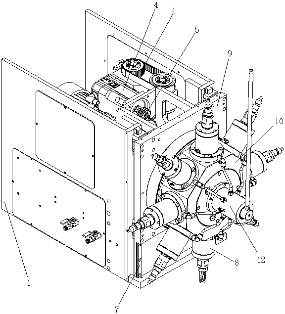
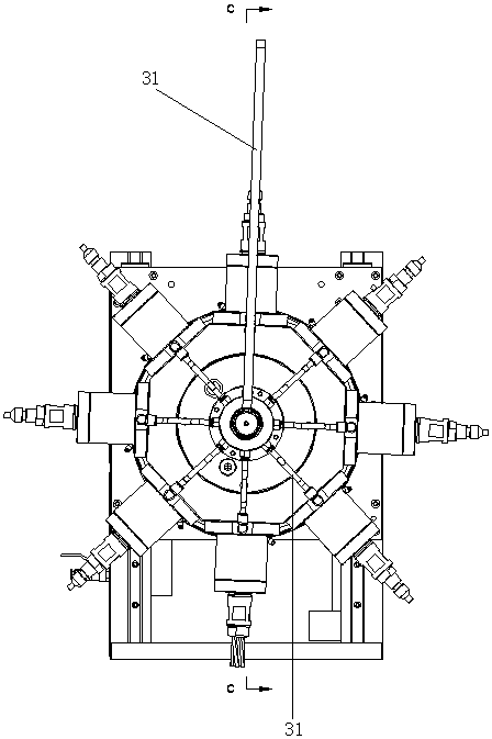
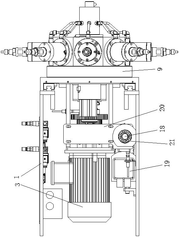
[0031] Below by embodiment and with reference to accompanying drawing, the present invention will be further described.

[0032] see Figure 1 to Figure 6 , the punching machine of the present invention includes a frame 1, a main shaft 2, a main drive motor 3, a central controller, a tool selection device, a head lifting device, a tool drive module 8 (head), a head mounting plate 9, Tool drive module mounting seat 10, tool cooling device 12, driving gear 13. The cutter driving module 8 is installed on the cutter driving module mounting seat 10, and the cutter driving module mounting seat 10 is installed on the machine head mounting plate 9 and can perform circular rotation. The head mounting plate 9 is installed on the guide rail 7, and the guide rail 7 is installed on the frame 1. The head lifting device is connected with the head mounting plate 9 to realize the overall movement of the head up and down. The main drive motor 3 and the driving gear 13 are respectively instal...


PUM


Abstract

The invention relates to a punching machine and a punching method. The punching machine comprises a machine frame, a tool drive power device, a central control unit, a tool selecting device, a machine head lifting device, tool drive modules, a tool drive module mounting base and a tool cooling device, wherein the tool drive modules are evenly installed on the tool drive module mounting base in the circumferential direction of a machine head mounting board; the tool drive module mounting base is installed on the machine head mounting board in a rotating mode; the machine head mounting board is installed on the machine frame in a sliding mode; the machine head lifting device is installed on the machine frame and connected with the machine head mounting board; the tool drive power device is installed on the machine head mounting board and matched with the tool drive modules; the tool selecting device is installed on the machine head mounting board and matched with the tool drive module mounting base; and the tool cooling device is connected with the tool drive modules through the tool drive module mounting base. According to the punching machine and the punching head, proper machine heads can be selected automatically, operation is easy, the degree of automation is high, control is accurate and fine, the manufacturing cost is low, and the service life is long.

Description

technical field [0001] The invention relates to a punching processing equipment, in particular to a multi-head punching machine and a punching method thereof, which are mainly used for punching holes in glass and plate materials. Background technique [0002] Existing drilling equipment usually only has one drill bit. Due to the inconsistency of materials and applications, the type, shape and size of the drill bit are also different, so that the drill bit needs to be reinstalled every time the hole is drilled, wasting a lot of manpower and time. In addition, after continuous drilling, the temperature of the drill bit increases due to high-speed rotation, which may easily lead to mechanical fatigue and damage, thereby affecting or limiting the ability, effect and accuracy of continuous processing. The patent name is "multi-head punching machine" and the patent document with the publication number CN 204711261 U discloses a punching machine that can process cylinders such as n...

Claims


Application Information

Patent Timeline
Patent Type & Authority Patents(China)
IPC IPC(8): B23B39/16B23B39/24B23B47/26B23Q5/40B23Q11/10B23Q5/20B23B47/06B23B47/22
CPCB23B39/168B23B39/24B23B47/26B23B2226/45B23Q5/043B23Q5/10B23Q5/20B23Q5/26B23Q5/28B23Q5/40B23Q11/10
Inventor 汤姆·佩廷
Owner ZHEJIANG DEMAN MACHINE
Why Eureka
Try Eureka