
Multi-angle drilling device

A drilling device, multi-angle technology, applied in drilling/drilling equipment, portable drilling rigs, workbenches, etc., can solve the problems of low processing efficiency, angle limitation, high cost, save production cost, improve work efficiency, The effect of reducing labor intensity

Active Publication Date: 2016-08-03
ZHEJIANG GEELY AUTOMOBILE +2
View PDF5 Cites 26 Cited by
  • Summary
  • Abstract
  • Description
  • Claims
  • Application Information

AI Technical Summary

Problems solved by technology

[0002] In the manufacturing industry, especially in stamping plants that use molds for production, it is often necessary to drill holes on the mold surface or blank holder when repairing the mold. Due to the complexity of the mold surface or blank holder, there are many The surface is inclined. At this time, the commonly used drilling machine or manual drilling method has the following defects: 1) The general drilling machine can only drill holes in the vertical Z-axis direction, which cannot be realized on the complex surface of the mold and the blank holder. Drilling, the angle is limited; 2) Drilling with a hand-held electric drill, the drilling needs to be adjusted repeatedly due to the inconsistency of the feed rate of the manual drilling, so drilling on the complex mold surface and blank holder ring, both It wastes time and increases the labor intensity of employees, the surface quality of the hole wall is difficult to guarantee, and the processing efficiency is low
The disclosed technology can realize multi-angle drilling, the effect is good, and the hole precision is also high, but the volume is large, and it is not suitable for the narrow space of mold maintenance, especially the structure of adjusting the angle is complicated and the cost is high

Method used


Image

  • Multi-angle drilling device
  • Multi-angle drilling device
  • Multi-angle drilling device

Examples


Embodiment

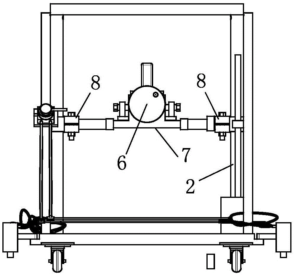
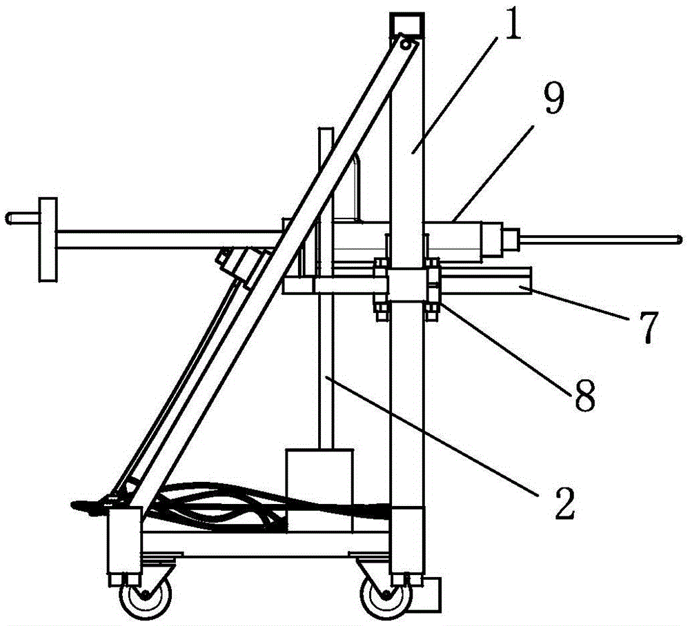
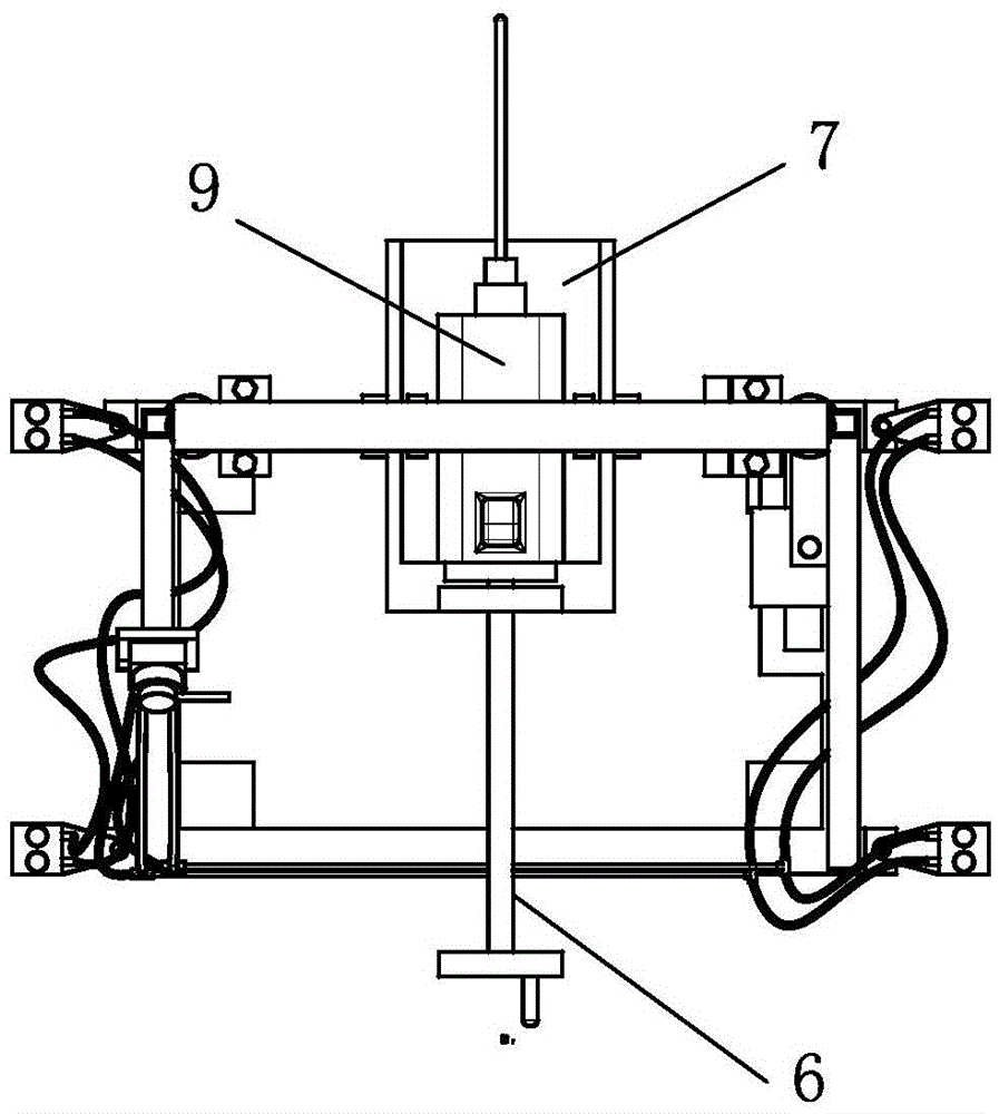
[0019] Embodiment: a kind of multi-angle drilling device of the present invention, as attached figure 1 , attached figure 2 , attached image 3 , attached Figure 4 As shown, it includes a fixed frame 1 with a base, the fixed frame 1 is provided with a slide rail and an electric drill fixed table 7 that moves up and down along the slide rail; the electric drill fixed table 7 is provided with a tray for fixing the electric drill 9, and the drive tray is on The feeding device 6 that moves back and forth on the electric drill fixed table 7.

[0020] The electric drill fixed table 7 is placed horizontally, and the left and right ends are shaft structures, and the shafts at both ends are coaxially arranged and connected on the slide seat of the slide rail through bearings. The bearing connection structure enables the electric drill fixing table 7 and the electric drill on it to rotate as a whole, so that the angle of the drill bit can be adjusted according to the angle requirem...


PUM


Abstract

The invention relates to a multi-angle drilling device. The multi-angle drilling device comprises a fixing frame provided with a base. The fixing frame is provided with a sliding rail and an electric drill fixing platform which moves up and down along the sliding rail. The electric drill fixing platform is transversely arranged, the left end and the right end of the electric drill fixing platform are of a shaft structure, and shaft parts of the two ends are coaxial and are connected to sliding bases of the sliding rail through bearings. The electric drill fixing platform is provided with a tray for fixing an electric drill and a feeding unit used for driving the tray to move front and back on the electric drill fixing platform. The device is adjusted to a proper height through ascent and descent, the angle of the fixing frame in the horizontal direction is adjusted, the electric drill fixing platform is rotated to adjust the angle in the vertical direction, and thus through the adjustment in the three aspects, an electric drill bit can rapidly arrive at an accurate position of a hole to be drilled, then the electric drill is started, and the feeding unit is used for performing drilling operation. The angle adjusting structure is simple, moving and angle adjusting operation is rapid, and the drilling efficiency is high.

Description

technical field [0001] The invention relates to a hole processing equipment, in particular to a multi-angle drilling device. Background technique [0002] In the manufacturing industry, especially in stamping plants that use molds for production, it is often necessary to drill holes on the mold surface or blank holder when repairing the mold. Due to the complexity of the mold surface or blank holder, there are many The surface is inclined. At this time, the commonly used drilling machine or manual drilling method has the following defects: 1) The general drilling machine can only drill in the vertical Z-axis direction, which cannot be realized on the complex surface of the mold and the blank holder. Drilling, the angle is limited; 2) Drilling with a hand-held electric drill, the drilling needs to be adjusted repeatedly due to the inconsistency of the feed rate of the manual drilling, so drilling on the complex mold surface and blank holder ring, both It wastes time and incr...

Claims


Application Information

Patent Timeline
IPC IPC(8): B23B45/02B23B45/14
CPCB23B45/02B25H1/0021B25H1/0078
Inventor 朱立赞邓林青
Owner ZHEJIANG GEELY AUTOMOBILE
Features
  • Generate Ideas
  • Intellectual Property
  • Life Sciences
  • Materials
  • Tech Scout
  • Unparalleled Data Quality
  • Higher Quality Content
  • 60% Fewer Hallucinations
Learn More