Grid cutting equipment

A technology for cutting equipment and grids, applied in shearing machine equipment, metal processing equipment, devices for cutting with nibbling action, etc., can solve problems such as environmental pollution, increase energy consumption, and increase production costs, and solve uneven distribution. , Improve the distribution effect, improve the effect of retention time

Active Publication Date: 2016-08-03
CHISEN POWER JIANGSU CO LTD
View PDF12 Cites 5 Cited by
  • Summary
  • Abstract
  • Description
  • Claims
  • Application Information

AI Technical Summary

Problems solved by technology

[0006] None of the above technical solutions are designed with cooling facilities. Therefore, in the conventional process, it is necessary to artificially pour emulsified oil. Due to the uneven amount of dripping, there will be too much saponified oil on the grid. When the grid appearance is unqualified, it needs to be inspected. Scrapped and returned to the furnace, and the grid scrapped and returned to the furnace will cause environmental pollution, increase energy consumption, and increase production costs
[0007] Therefore, people have developed a grid splitter with cooling measures. The Chinese patent document with the publication number CN105344979A discloses a cooling device for a grid splitter, including a base, which is provided with a transport grid for transporting the grid. Belt, the top of the base is provided with a knife seat for installing a circular saw blade. The saw blade corresponds to the conveyor belt. The other end of the oil pipe is connected to the oil barrel, and a control valve is set at the connection between the oil pipe and the oil barrel; the oil pipe is provided to provide paraffin oil for the saw blade to reduce the high temperature of the saw blade to solve the existing problem The problem that the temperature of the saw blade of the panel machine is too high affects the performance of the product
In this technical solution, the method of spraying cooling grease is adopted by referring to the traditional cooling method, but the paraffin oil is prone to uneven distribution during the spraying process

Method used


Image

  • Grid cutting equipment
  • Grid cutting equipment
  • Grid cutting equipment

Examples


Embodiment Construction

[0034] The specific embodiments of the present invention will be described below in conjunction with the accompanying drawings.

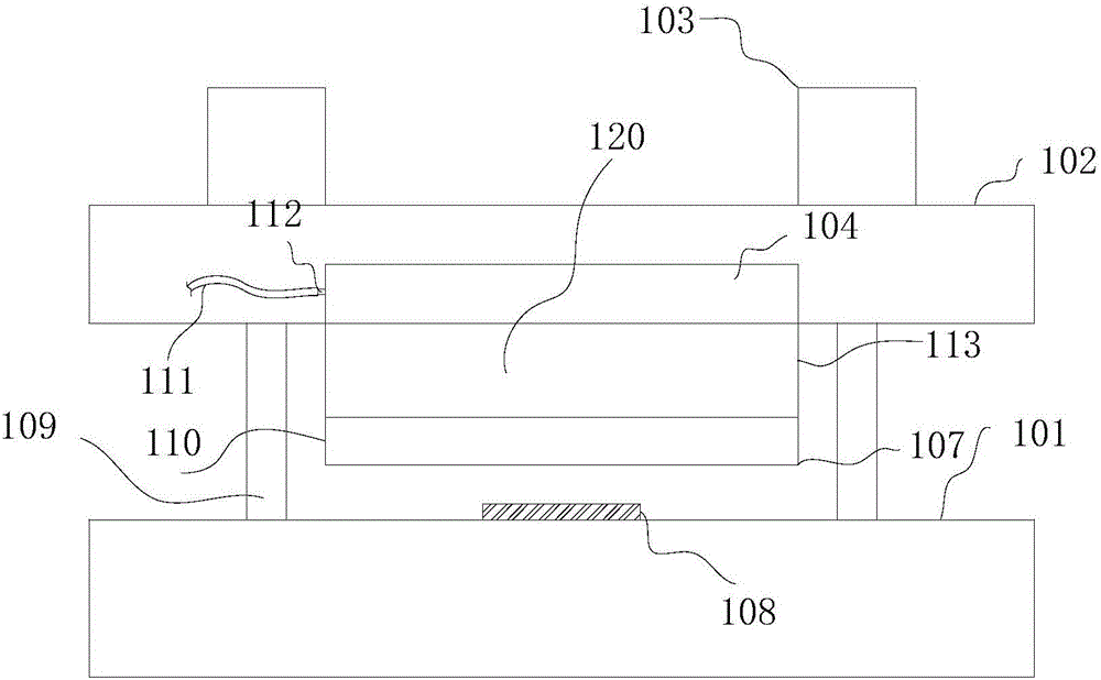
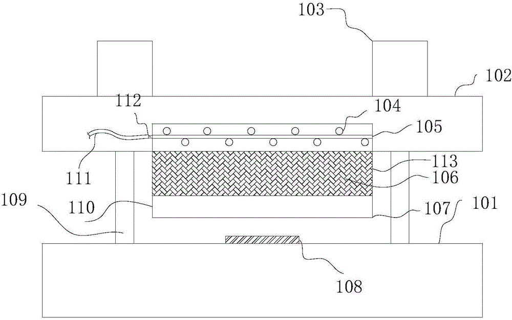
[0035] like Figure 1~3 As shown, a grid cutting equipment includes a frame 101 provided with a grid conveyor belt and a knife frame 102 mounted on the frame 101 and capable of moving relative to the frame 101. The tool frame 102 is provided with a hydraulic cylinder 103. The piston rod 109 of the hydraulic cylinder 103 is fixed to the frame 101, and the hydraulic cylinder 103 is provided with two groups.

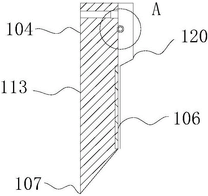
[0036] A cutter 110 for cutting the grid 108 is installed on the knife rest 102, and a dust cover 120 wrapping the tail portion 104 and the cutter body 113 is installed on the cutter 110. The frame 101 is divided into successively: the tail portion 104 for fixing with the knife rest 102, the cutter body 113 protruding from the knife rest 102 and the blade portion 107 for interacting with the grid 108; The cooling pipeline of the heat exchange m...


PUM

PropertyMeasurementUnit
depthaaaaaaaaaa

Abstract

The invention discloses grid cutting equipment which comprises a rack provided with a grid conveyor belt and a tool rest arranged on the rack and capable of moving relative to the rack, wherein a cutter used for cutting a grid is arranged on the tool rest, the cutter is of an integrated structure and is sequentially divided into a tail part fixed with the tool rest, a cutter body exposed from the cutter rest and a blade part acting with the grid from the tool rest to the rack; a cooling pipeline used for providing a heat exchange medium to the blade part is fixed on the tail part, and the cooling pipeline is externally wrapped with a porous material used for uniformly distributing the heat exchange medium; distribution lines used for dispersing the heat exchange medium are arranged on the cutter body; and the cutter is provided with a dust cap wrapping the tail part and the cutter body. According to the invention, the design that the porous material wraps a cooling pipeline is adopted, so that uniform distribution of the heat exchange medium on the surface of the cutter body is improved; the design of distribution lines is adopted; and the design of a heat exchange trough is adopted.

Description

technical field [0001] The invention relates to the field of storage battery manufacturing, in particular to grid cutting equipment. Background technique [0002] The grid is the main component of the lead-acid battery. In order to improve the production efficiency in the production process, it is generally produced in the form of multi-connected plates. Therefore, it is necessary to cut the multi-connected plates into suitable sizes. When cutting the knife, it is easy to cause curling and cutting damage due to high temperature. [0003] For example: the Chinese patent document whose publication number is CN203265779U discloses a cutting machine for cutting battery electrode plate grids. It includes a frame, on which a set of saw blades composed of multiple coaxial saw blades is arranged, a conveyor belt is also arranged in front of the saw blades, and a conveyor belt is also arranged on the frame. The saw blade drive machine that drives the saw blade set to rotate and the...

Claims


Application Information

Patent Timeline
Patent Type & Authority Applications(China)
IPC IPC(8): B23D27/00B23Q11/10B23D35/00
CPCB23D27/00B23D35/001B23Q11/10
Inventor 张建南徐克成胡亚军闫瑞刚张琳
Owner CHISEN POWER JIANGSU CO LTD
Why Eureka
Try Eureka