Tubular part welding rapid butt-joint positioning device

A technology for positioning devices and tubular parts, which is applied in the direction of auxiliary devices, welding equipment, auxiliary welding equipment, etc., can solve the problems of unguaranteed welding accuracy and pipeline coaxiality, unfavorable on-site operation, construction space constraints, etc., to achieve shortening The effect of workload, easy to master, and small investment

Inactive Publication Date: 2016-08-03
SHANGHAI UNIV OF ENG SCI
View PDF8 Cites 13 Cited by
  • Summary
  • Abstract
  • Description
  • Claims
  • Application Information

AI Technical Summary

Problems solved by technology

In piping engineering, the welding of pipe joints occupies a large workload. The conventional manual welding method is time-consuming and laborious, and the welding accuracy and the coaxiality of the pipes cannot be guaranteed, which is prone to middle misalignment and uneven weld seams and other problems; the existing welding construction device needs a variety of equipment to be used in conjunction, and the equipment is easily restricted by the limited construction space when erecting the equipment, which is not conducive to on-site operation, and there are insurmountable technologies such as difficult matching and welding seam adjustment during specific operations question

Method used


Image

  • Tubular part welding rapid butt-joint positioning device
  • Tubular part welding rapid butt-joint positioning device
  • Tubular part welding rapid butt-joint positioning device

Examples


Embodiment Construction

[0031] The present invention will be further described below in conjunction with accompanying drawing.

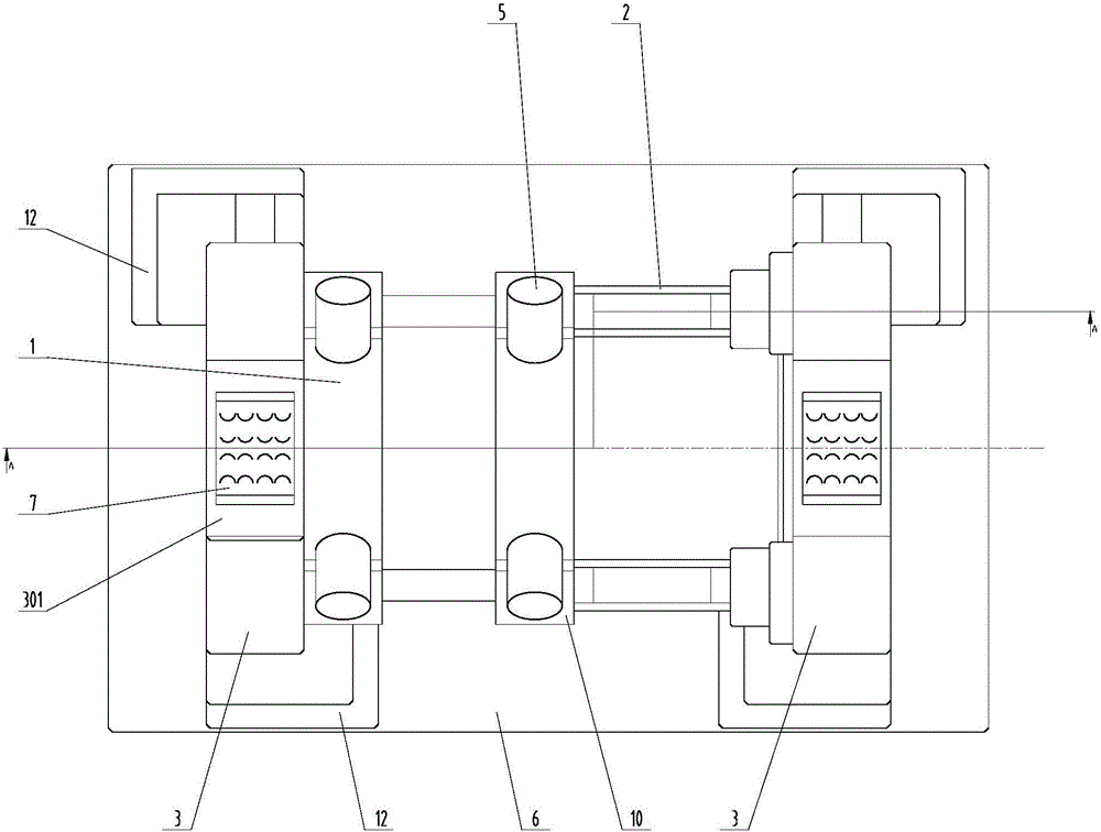
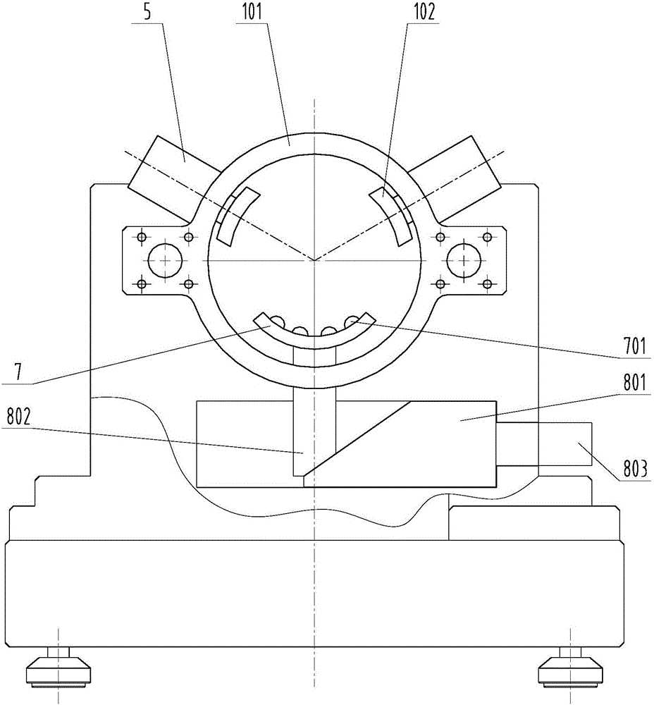
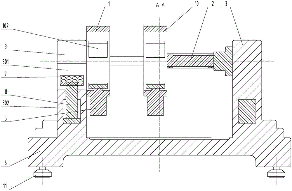
[0032] Such as Figure 1~4 As shown, on the horizontal support base 6, a pair of "U"-shaped support frames 3 with an upward opening are vertically spaced and parallelly fixed by two pairs of right-angled bending support angles 12, and the bottom of the support base 6 is provided with shock-absorbing support feet 11. The right-angle outer sides of the bottom of the support frame 3 are respectively close to the right-angle inner sides of the right-angle bending support angle 12, and the right-angle bending support angle 12 is fixed on the support base 6 by a plurality of bolts arranged at intervals, which plays a greater role in the support frame 3. Good stopper action.

[0033] The fixed clamping assembly 1 and the movable clamping assembly 10 are coaxially arranged on the inner side of the support frame 3. The fixed clamping assembly 1 is fixedly installed on one support f...


PUM


Abstract

The invention discloses a tubular part welding rapid butt-joint positioning device. A fixed clamping assembly and a movable clamping assembly are coaxially arranged in a spaced mode on the inner sides of a pair of supporting frames arranged in a spaced mode. The movable clamping assembly can be driven by a first pushing assembly to translate in the axial direction so as to change the distance between the fixed clamping assembly and the movable clamping assembly. Through grooves are formed in the tops of the two supporting frames in the axial directions of the clamping assemblies correspondingly. Movable supporting blocks are arranged at the bottoms of the through grooves. A plurality of universal balls are movably installed on the movable supporting blocks at intervals and can rotate on the movable supporting blocks. The tops of the universal balls are exposed out of the upper portions of the movable supporting blocks to form supporting faces. The movable supporting blocks can be pushed by a third pushing assembly to move in the depth direction of groove cavities of the through grooves. The device further comprises a plurality of independently separated buffer gaskets with different thicknesses. The device is simple and compact in structure, positioning is accurate, operation is simple and the safety performance is high.

Description

technical field [0001] The invention relates to the field of mechanical processing, in particular to an alignment technology for welding and butt jointing of tubular parts. Background technique [0002] Pipes of different materials, especially when metal pipes or PP pipes need to be butt-jointed, are currently commonly used in the industry for pipe hot-melt welding, pipe thread connection, pipe flange connection and other connection methods. In piping engineering, the welding of pipe joints occupies a large workload. The conventional manual welding method is time-consuming and laborious, and the welding accuracy and the coaxiality of the pipes cannot be guaranteed, which is prone to middle misalignment and uneven weld seams. and other problems; the existing welding construction device needs a variety of equipment to be used in conjunction, and the equipment is easily restricted by the limited construction space when erecting the equipment, which is not conducive to on-site o...

Claims


Application Information

Patent Timeline
Patent Type & Authority Applications(China)
IPC IPC(8): B23K37/053
CPCB23K37/0533
Inventor 张哲皓杜继涛王浩杨梅谷星熠盛文超盛屹
Owner SHANGHAI UNIV OF ENG SCI
Why Eureka
Try Eureka