High-precision machining machine tool

A high-precision machining and machine tool technology, applied in metal processing machinery parts, metal processing equipment, manufacturing tools, etc., can solve the problems of single structure, unfavorable, and the position of the processing tool cannot be moved in all directions.

Inactive Publication Date: 2016-08-03
ZHENJIANG FUDE NC MACHINE TOOL TECH CO LTD
View PDF6 Cites 2 Cited by
  • Summary
  • Abstract
  • Description
  • Claims
  • Application Information

AI Technical Summary

Problems solved by technology

However, the existing processing machine tools usually have a single structure, and the position of the processing tool cannot be moved in all directions, which is not conducive to processing any position on the surface of the workpiece when the workpiece is fixed.

Method used


Image

  • High-precision machining machine tool

Examples


Embodiment Construction

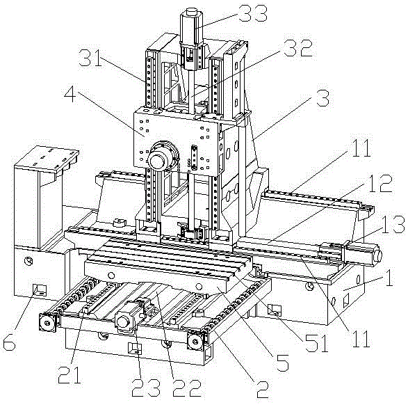
[0012] The present invention will be further described below in conjunction with the accompanying drawings.

[0013] Such as figure 1 As shown, a high-precision processing machine tool includes a base 1, a support platform 2 is provided on one side of the base 1, and a workbench 5 that can move back and forth relative to it is provided on the support platform 2. On the base 1, A saddle 3 that can move left and right relative to it is provided, and a main shaft 4 that can move up and down relative to it is provided on the saddle 3, and a control cabinet 6 is also provided at one end of the base 1, wherein the base 1 is a step shape, the height of the workbench 5 is consistent with the height of the lower step surface of the base 1 .

[0014] By designing the saddle to move left and right relative to the base, designing the spindle to move up and down relative to the saddle, and designing the workbench to move forward and backward relative to the base, the spindle can adjust it...


PUM


Abstract

The invention discloses a high-precision machining machine tool. The high-precision machining machine tool comprises a base, a supporting platform is arranged on one side of the base, and a workbench which can move back and forth relative to the supporting platform is arranged on the supporting platform. The base is provided with a saddle which can move left and right relative to the base, and the saddle is provided with a main shaft which can move up and down relative to the saddle. A control cabinet is arranged at one end of the base. The base is in a step shape, and the height of the workbench is consistent with the height of a low step face of the base. Due to the fact that the saddle is designed to move left and right relative to the base, the main shaft is designed to move up and down relative to the saddle, and the workbench is designed to move back and forth relative to the base, the main shaft can be adjusted to corresponding positions according to positions of a workpiece, and the machine tool is suitable for machining any position on the surface of the workpiece.

Description

technical field [0001] The invention relates to a high-precision processing machine tool, which belongs to the technical field of machine tool processing. Background technique [0002] Machine tools are indispensable equipment in the modern industrial production process and are used to process raw materials. However, the existing processing machine tools usually have a single structure, and the position of the processing tool cannot be moved in all directions, which is not conducive to processing any position on the surface of the workpiece when the workpiece is fixed. Contents of the invention [0003] The technical problem to be solved by the present invention is to provide a high-precision machining machine tool. Through the design of corresponding guide rails, the main shaft can move up and down, left and right, and forward and backward, and only need to fix the workpiece on the workbench. [0004] In order to solve the problems of the technologies described above, th...

Claims


Application Information

Patent Timeline
IPC IPC(8): B23Q1/58B23Q1/62
CPCB23Q1/621B23Q1/58
Inventor 任革富
Owner ZHENJIANG FUDE NC MACHINE TOOL TECH CO LTD
Why Eureka
Try Eureka