Adjustable thread tube carrying table structure
A placing table and adjustable technology, which is applied in the field of quilting, can solve the problems of low space utilization rate of the suture output part, the inability to realize the suture barrel and the thread outlet, and the limited distance of suture output arrangement, etc., so as to achieve convenience and efficiency. Sequential output, reduced risk of disconnection, and high space utilization
- Summary
- Abstract
- Description
- Claims
- Application Information
AI Technical Summary
Problems solved by technology
Method used
Image
Examples
Embodiment 1
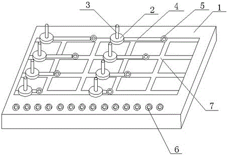
[0027] Such as Figure 1~3 As shown, the structure of an adjustable suture barrel placement platform described in this embodiment includes a placement platform body 1 and a number of receiving supports for placing suture barrels arranged on the placement platform body 1 and for leading out seams. The lead-out ring 6 of the wire, the lead-out ring 6 is arranged on the upper edge of one side of the placing table body 1, and the placing table body 1 is provided with a grid-shaped sliding groove 7, and the receiving support is placed in the sliding groove 7, and each The receiving support can move to any position of the slide groove 7 . Preferably, the receiving supports on the placing table body 1 of this embodiment are arranged in rows and rows.
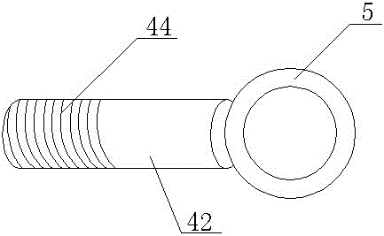
[0028] The receiving support of this embodiment includes a round table 2, an insertion rod 3, a support rod 4 and a guide ring 5, the insertion rod 3 is fixed on the round table 2 in a vertical state, and the support rod 4 is fixed on...
Embodiment 2
[0032] Such as Figure 4 As shown, this embodiment is basically the same as Embodiment 1, the difference is that an opening 51 is provided on the guide ring 5 of this embodiment, even if the suture on the suture cylinder has been connected to the suture needle, it can also achieve support. To adjust the length of the rod 4, you only need to move the suture out of the guide ring 5 through the opening 51, then rotate the second adjustable part 42 to adjust the rod 4 to a suitable length, and then move the suture into the guide ring, so that the rod Length adjustment of 4 becomes easy.
Embodiment 3
[0034] Such as Figure 5 As shown, on the basis of embodiment 1 or embodiment 2, this embodiment also includes a guide locking device, the guide lock device includes a bolt 8 and a slider 9, one end of the bolt 8 is fixed on the bottom of the round table 2, and the other end Realize threaded connection with slide block 9, the longitudinal section shape of slide groove 7 is T shape, slide block 9 is placed on the bottom of slide groove 7, slide block 9 and bolt 8 form T shape, matches with the shape of slide groove 7, in Under the action of the slider 9, the round table 2 always moves along the predetermined route of the sliding groove 7 and reaches the desired position during the moving process, and then the round table 2 is rotated to realize the position locking of the round table 2.
[0035] This embodiment adopts the above-mentioned structure, which can facilitate the adjustment and locking of the position of the round platform, and at the same time simplify the entire gui...
PUM
 Abstract
Description
Claims
Application Information
 - R&D
- Intellectual Property
- Life Sciences
- Materials
- Tech Scout
- Unparalleled Data Quality
- Higher Quality Content
- 60% Fewer Hallucinations
Browse by: Latest US Patents, China's latest patents, Technical Efficacy Thesaurus, Application Domain, Technology Topic, Popular Technical Reports.
© 2025 PatSnap. All rights reserved.Legal|Privacy policy|Modern Slavery Act Transparency Statement|Sitemap|About US| Contact US: help@patsnap.com


