Low-power-consumption, adjustable-frequency and adjustable-duty-ratio clock generation circuit

A clock generation circuit and frequency modulation technology, which is applied in the direction of electric pulse generation, pulse generation, multiple input and output pulse circuits, etc., can solve the problems of unfavorable overall system miniaturization, large overall power consumption, and difficulty in modifying traditional crystal oscillator circuits.

Active Publication Date: 2017-07-18
XIDIAN UNIV
View PDF5 Cites 5 Cited by
  • Summary
  • Abstract
  • Description
  • Claims
  • Application Information

AI Technical Summary

Problems solved by technology

This method has a large overall power consumption and complex structure, which is not conducive to the miniaturization of the overall system.
In addition, for appl

Method used


Image

  • Low-power-consumption, adjustable-frequency and adjustable-duty-ratio clock generation circuit
  • Low-power-consumption, adjustable-frequency and adjustable-duty-ratio clock generation circuit
  • Low-power-consumption, adjustable-frequency and adjustable-duty-ratio clock generation circuit

Examples


Embodiment 1

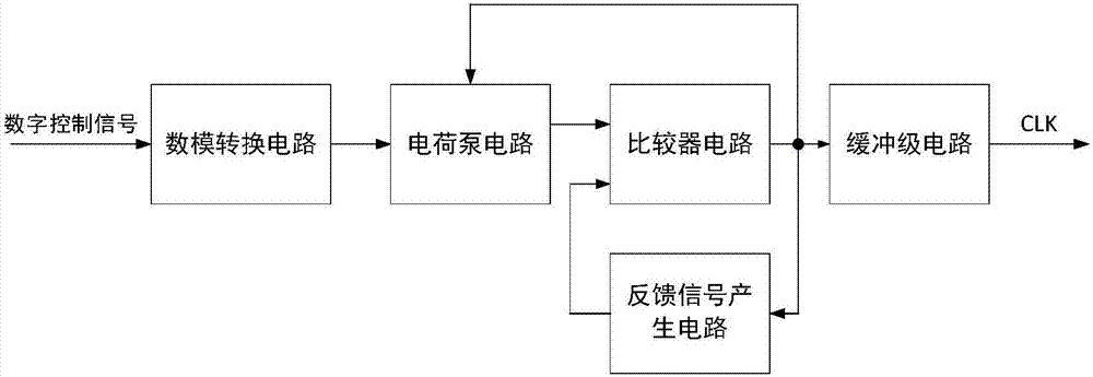
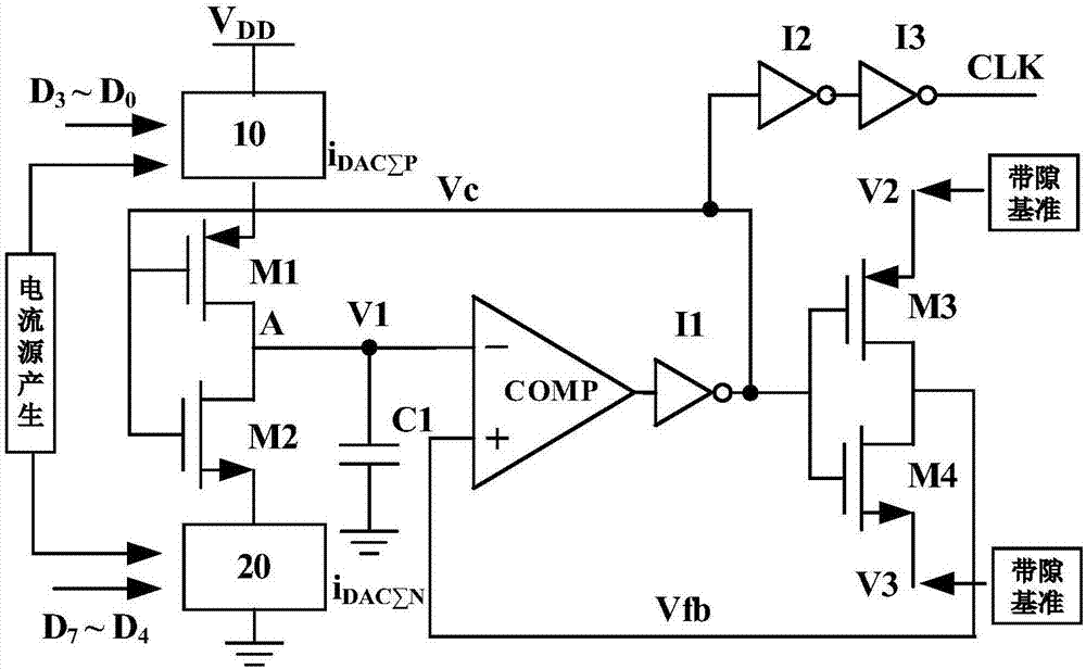
[0033] Please refer to figure 1 , figure 2 , figure 1 A structural block diagram of a clock generation circuit with low power consumption, adjustable frequency, and adjustable duty cycle provided by an embodiment of the present invention; figure 2 A schematic structural diagram of a low power consumption adjustable frequency and adjustable duty cycle clock generation circuit provided by an embodiment of the present invention; the low power consumption adjustable frequency and adjustable duty cycle clock generation circuit includes: digital-analog A conversion circuit, a charge pump circuit, a comparator circuit, a feedback signal generation circuit and a buffer stage circuit, the digital-to-analog conversion circuit receives a digital control signal and is electrically connected to the charge pump circuit, and the charge pump circuit is electrically connected to the comparator circuit, the comparator circuit is electrically connected to the feedback signal generating circu...

Embodiment 2

[0050] In this embodiment, on the basis of the above-mentioned embodiments, the working principle and connection relationship thereof will be further described with emphasis.

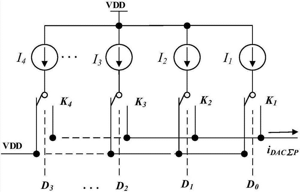
[0051] see again figure 1 , the digital-to-analog converter 10 adopts a binary-weighted current-source-steering DAC (current-steering DAC). It receives an external digital control signal (binary code), which is used to adjust the current i of the P-type current steering DAC DACΣP and the current i of the N-type current steering DAC DACΣN The size of the charge pump can be adjusted to adjust the charge and discharge current of the charge pump, and the duty cycle adjustment function of the clock generation circuit can be realized. This digital control signal is the duty ratio setting value. The current steering DAC in the digital-to-analog converter has fast switching speed and strong driving capability, and can obtain high output current precision.

[0052] The current source generating circuit recei...


PUM


Abstract

The invention relates to a low-power-consumption, adjustable-frequency and adjustable-duty-ratio clock generation circuit. The low-power-consumption, adjustable-frequency and adjustable-duty-ratio clock generation circuit is characterized in that the circuit includes a DAC (Digital-to-Analogue Conversion) circuit, a charge pump circuit, a comparator circuit, a feedback signal generating circuit and a buffer stage circuit; the DAC circuit receives digital control signals and is electrically connected to the charge pump circuit; the charge pump circuit is electrically connected to the comparator circuit; the comparator circuit is electrically connected to the feedback signal generating circuit and the buffer stage circuit; and the buffer state circuit outputs clock signals CLK. According to the invention, stable, precise adjustable-frequency and adjustable duty-ratio clock signal output can be obtained. Besides, the charge pump circuit is simple in structure and is insusceptible to influence of technique, temperature and voltage change. The clock signal output path is extremely simple and a low signal jitter characteristic is realized.

Description

technical field [0001] The invention belongs to the technical field of integrated circuit design, and in particular relates to a clock generating circuit with low power consumption, adjustable frequency and adjustable duty cycle. Background technique [0002] The ever-growing market for portable electronics has spurred academic research on high-performance, low-power, low-voltage electronic systems. SOC-on-chip mixed-signal systems are a high-performance, low-cost solution for a wide range of audio-frequency portable electronics. How to realize the design of low power consumption and low voltage in SOC system has become an important research topic. [0003] In response to this trend, the continuous-time audio sigma-delta ADC reduces the design requirements for analog circuits by using oversampling, noise shaping and digital filtering techniques, and achieves high precision and low power consumption that cannot be achieved by other types of ADCs. However, with the increase ...

Claims


Application Information

Patent Timeline
IPC IPC(8): H03K3/017H03M1/86H03K5/22
CPCH03K3/017H03K5/22H03M1/86
Inventor 晋超超白文彬朱樟明李娅妮杨银堂
Owner XIDIAN UNIV
Why Eureka
Try Eureka