Dismounting device

A technology for dismantling devices and power devices, which is applied to mining equipment, earth square drilling, mine roof supports, etc., can solve the problems of high labor intensity, poor work safety, and potential safety hazards for workers, and improve work efficiency and work safety , Reduce labor intensity, avoid the effect of falling

Inactive Publication Date: 2016-08-03
SHANDONG MINING MASCH GRP CO LTD
View PDF4 Cites 2 Cited by
  • Summary
  • Abstract
  • Description
  • Claims
  • Application Information

AI Technical Summary

Problems solved by technology

Thereby in the work, after the coal of a certain area is mined, need to remove the I-beam support 13, the dismantling mode of the I-beam support 13 at present stage is manual dismantling, not only the labor intensity of the staff is big, and, in During the dismantling process, the work safety is poor (after the I-beam support 13 is dismantled, there is a risk of roof fall, and there is a great potential safety hazard)

Method used


Image

  • Dismounting device
  • Dismounting device
  • Dismounting device

Examples


Embodiment Construction

[0029] In order to make the object, technical solution and advantages of the present invention clearer, the present invention will be further described in detail below in conjunction with the accompanying drawings and embodiments. It should be understood that the specific embodiments described here are only used to explain the present invention, not to limit the present invention.

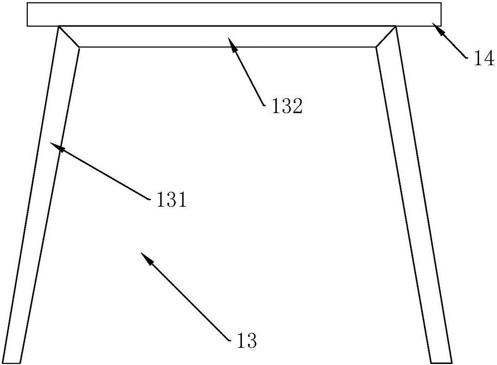
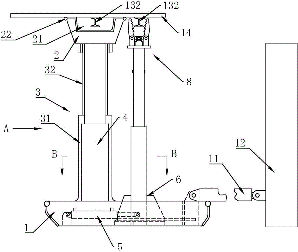
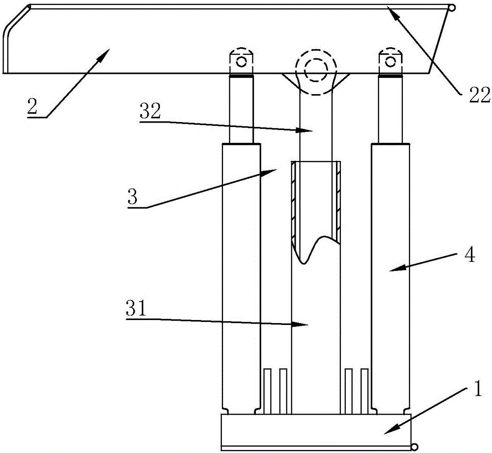
[0030] like Figure 2 to Figure 6 Commonly shown, a dismounting device includes a base 1 and a top beam 2, a guide mechanism 3 is provided between the base 1 and the top beam 2, and there are hinged joints between the base 1 and the top beam 2 on both sides of the guide mechanism 3. The first power device 4; the guide mechanism 3 includes a guide cylinder 31 arranged on the base 1, a guide column 32 hinged on the top beam 2 is slidably installed in the guide cylinder 31, and the length of the guide column 32 is greater than that of the first power unit. The stroke of device 4.

[0031] A sliding ...


PUM


Abstract

The invention discloses a dismounting device. The dismounting device comprises a base and a top beam, wherein a guide mechanism is arranged between the base and the top beam; a first power device is hinged between the base and the top beam, which are located on the two sides of the guide mechanism; the base is further provided with a slide seat, which is driven by a second power device, in a sliding manner; and the slide seat is internally and vertically provided with at least two grasping mechanisms, which are driven by a third power device, in a sliding manner. With the adoption of the dismounting device disclosed by the invention, the labor intensity of workers is greatly alleviated, and the working efficiency and the working safety are improved; and meanwhile, a top plate is supported stably and reliably, a danger that the top plate cap falls off is avoided, and thus the working safety is further improved.

Description

technical field [0001] The invention relates to a dismounting device. Background technique [0002] In the field of coal mining machinery and equipment, those skilled in the art know that the support in the roadway is mainly supported by an I-shaped steel support 13, and the top of the I-shaped steel support 13 is supported by a top plate 14 (this I-shaped steel support 13 includes The I-shaped steel supporting legs 131 on both sides and the I-shaped steel top beam 132 at the top of the I-shaped steel supporting legs 131, the I-shaped steel top beam 132 and the I-shaped steel supporting legs 131 are fixedly connected together, see figure 1 ). Thereby in the work, after the coal of a certain area has been mined, the I-beam support 13 needs to be dismantled. In the process of dismantling, work safety is poor (after the I-beam support 13 is dismantled, there is the danger of roof fall, and there is a great potential safety hazard). Contents of the invention [0003] The pu...

Claims


Application Information

Patent Timeline
Patent Type & Authority Applications(China)
IPC IPC(8): E21D23/04
CPCE21D23/04
Inventor 冯坤赵兰芳王红青王建祥王振李佐冯传军周爱亮戴立民
Owner SHANDONG MINING MASCH GRP CO LTD
Why Eureka
Try Eureka