Plunger type oil diaphragm pump

A diaphragm pump and plunger technology, applied in the field of plunger oil diaphragm pump, can solve the problems of difficult operation, troublesome adjustment of three valves, leakage of methanol, etc., to achieve low friction power consumption, superior sealing conditions and long life. Effect

Active Publication Date: 2016-08-03
NINGBO HELI MECHANICAL PUMP CO LTD
View PDF7 Cites 1 Cited by
  • Summary
  • Abstract
  • Description
  • Claims
  • Application Information

AI Technical Summary

Problems solved by technology

The diaphragm metering pump separates the medium methanol from the sealing packing through the diaphragm to achieve zero leakage. However, the manufacturing cost of diaphragm metering pumps is generally high, and the processing technology and precision requirements are also very high. Especially the adjustment of the three valves is troublesome and professional. Strong, it is difficult for general users to operate, and the life of the diaphragm is not long, it is inconvenient to disassemble and replace the diaphragm, and a large amount of medium methanol will leak during the process

Method used


Image

  • Plunger type oil diaphragm pump
  • Plunger type oil diaphragm pump
  • Plunger type oil diaphragm pump

Examples


Embodiment 1

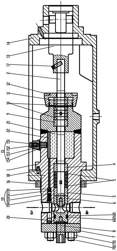
[0021] Such as image 3 The plunger type oil diaphragm pump shown includes a fluid end and a power end, wherein the fluid end includes: a hydraulic cylinder bracket 14; a crosshead 13, a positioning screw pin 17, a plunger 2; an adjusting nut 12, and an auxiliary pressure ring 11. Auxiliary packing 10, auxiliary guide sleeve 9; engine oil 21, medium (methanol) 22; manual air release valve assembly 15: air release plug 151, valve ball 152, valve chamber 153, gasket 154; pump body 1, cylindrical pin 18. Lock nut 16; return valve assembly 19: valve ball 191, valve cover 192, valve spring 193, screw plug bracket 194, screw plug 20; main pressure ring 4, main packing 5, main guide sleeve 3, pressure sleeve 6 , O-ring 601, retaining ring 602, adjusting bolt 8, flange 7, hex nut 701, stud 702.

[0022] The hydraulic cylinder bracket 14 is assembled with the power end fuselage for fixing the entire liquid end.

[0023] The pump body 1 is provided with a plunger passage and a valve g...

Embodiment 2

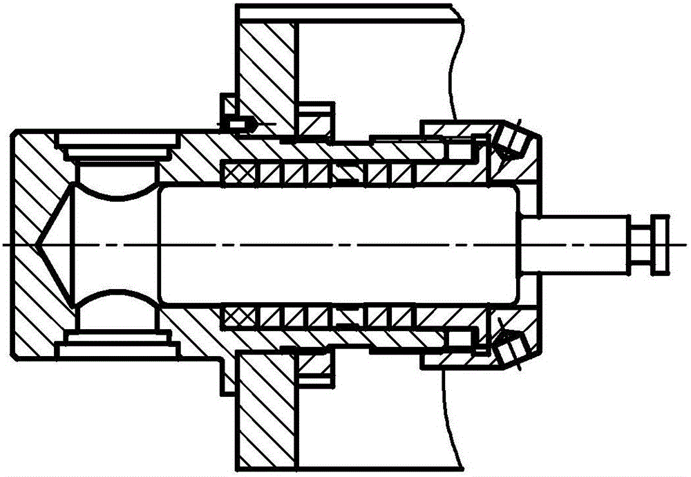
[0030] The difference from Embodiment 1 is that due to the difference in the medium, the position of the return valve cavity is set on the lower side of the pump body 1, the corresponding suction port is at the bottom, and the discharge port is at the top, see Figure 4shown. Specifically, the density of the conveying medium in this embodiment is higher than that of the engine oil 21, so the medium will sink below the engine oil 21, and the leaked medium will slowly fill the remaining cavity of the entire oil pool. When the pressure in the cavity is greater than 1 MPa, the return flow located below The valve assembly 19 will be opened, and the medium below the machine oil 21 will flow into the suction port through the return valve assembly 19 and be released to a certain amount. When the pressure in the chamber is less than 1 MPa, the return valve assembly 19 will automatically close. Since the pressure in the chamber is always less than 1MPa, the leakage of the auxiliary stuf...


PUM


Abstract

The invention relates to a plunger type oil diaphragm pump which comprises a hydraulic end and a power end. The hydraulic end comprises a pump body assembly, a plunger (2) arranged in the pump body assembly, and a hydraulic cylinder support (14) used for fixing the pump body assembly. The hydraulic cylinder support (14) and a machine body at the power end are assembled together to be used for fixing the hydraulic end. The pump body assembly comprises a pump body (1), and a plunger channel is arranged in the pump body (1). The plunger is movably arranged in the plunger channel, and a sealing box assembly is arranged between the plunger and the plunger channel. The plunger type oil diaphragm pump is characterized in that a main sealing cavity is formed in the front end of the plunger channel, and an auxiliary sealing cavity is formed in the rear end of the plunger channel; the sealing box assembly comprises a main stuffing box assembly arranged in the main sealing cavity and an auxiliary stuffing box assembly arranged in the auxiliary sealing cavity; an oil bath used for separating the main stuffing box assembly from the auxiliary stuffing box assembly is arranged in the portion, between a stuffing box and an auxiliary stuffing box, of the plunger channel; and the oil bath is filled with lubricating oil (21). According to the plunger type oil diaphragm pump, medium leakage is avoided, and the plunger is convenient to machine, assemble and disassemble.

Description

technical field [0001] The invention belongs to the technical field of mechanical automation, and in particular relates to a plunger-type oil diaphragm pump capable of transporting harmful media (such as methanol). Background technique [0002] The medium sealing part of the traditional plunger metering pump is composed of plunger, packing, guide sleeve, packing pressure ring and adjusting nut. figure 1 As shown, there are V-shaped, U-shaped, rectangular and other sealing forms to form a group of sealing belts. As the packing wears and the pressure increases, the medium will directly leak from the packing and plunger into the liquid cylinder. For the conveying medium is water or Non-toxic and harmless liquid, this kind of leakage is allowed, as long as the leakage does not exceed the national standard, a small amount of leakage can even increase the service life of the plunger and packing. However, for the delivery of harmful media such as methanol, the leakage generated at...

Claims


Application Information

Patent Timeline
Patent Type & Authority Applications(China)
IPC IPC(8): F04B15/00F04B53/02F04B53/10F04B53/04
CPCF04B15/00F04B53/02F04B53/04F04B53/1002
Inventor 陈明海葛溪陈英峰
Owner NINGBO HELI MECHANICAL PUMP CO LTD
Why Eureka
Try Eureka