Bearing pedestal oil cavity cleaning system and method, mineral engineering machine and engineering machine

A bearing seat and oil supply system technology, applied in chemical instruments and methods, cleaning methods and utensils, cleaning methods using liquids, etc., can solve the difficulty of bearing seat cleanliness, affect lubricant performance, and lubricating grease affect lubrication effect and other problems, to achieve good results in improving versatility and scope of application, automatic continuous cleaning, and lubrication, cleaning and lubrication.

Inactive Publication Date: 2016-08-03
长沙贤正益祥机械科技有限公司
View PDF0 Cites 2 Cited by
  • Summary
  • Abstract
  • Description
  • Claims
  • Application Information

AI Technical Summary

Problems solved by technology

[0004] However, with the growth of time, the deteriorated lubricating grease is stored in the cavity and affects the lubrication effect
After the parts in the bearing seat have been running for a long time, the dropped tiny metal particles and other substances will also increase in the bearing seat. They enter the bearing, which not only affects the performance of the lubricant, destroys the formed oil film, but also directly Cause abrasive wear, leading to early failure of bearing fatigue
The preventive measures that can be taken at present are mainly to disassemble the bearing seat for thorough cleaning, but to remove the bearing means to disassemble the shaft and its transmission parts in the bearing and clean them all, that is, overhaul
The scale of overhaul is huge, and it is very difficult to thoroughly clean the bearings, shafts and their accessories for equipment in harsh environmental conditions, and it is even more difficult to ensure the cleanliness of the bearing housing when reassembling

Method used


Image

  • Bearing pedestal oil cavity cleaning system and method, mineral engineering machine and engineering machine
  • Bearing pedestal oil cavity cleaning system and method, mineral engineering machine and engineering machine
  • Bearing pedestal oil cavity cleaning system and method, mineral engineering machine and engineering machine

Examples


Embodiment Construction

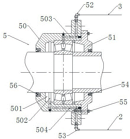
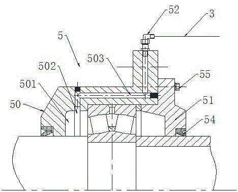
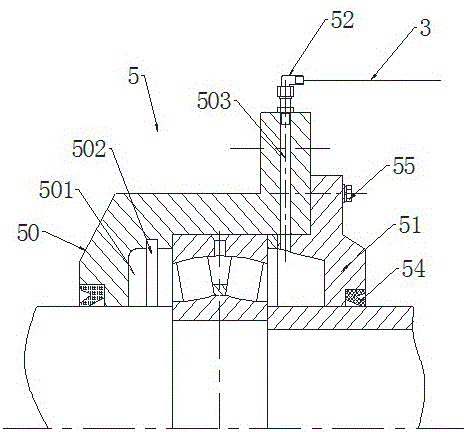
[0043] The purpose of the present invention is to provide a bearing seat, which has a simple structure, and can realize the cleaning of the oil chamber in the bearing seat without disassembling the bearing seat, bearing and related parts, and makes it possible to clean the bearing seat oil The method of removing impurities in the cavity is relatively simple. The second object of the present invention is to provide a bearing seat oil chamber cleaning and lubrication system based on the above-mentioned bearing seat. The bearing seat oil chamber cleaning and lubrication system has a simple structure, is safe and reliable, and has good cleaning and lubrication effects, and can realize the cleaning and lubrication of the bearing seat. Automatic cleaning and lubrication operations. The third object of the present invention is to provide a method for applying the above-mentioned bearing seat and its cleaning and lubricating system, which has the characteristics of simple operation an...


PUM


Abstract

The invention discloses a bearing pedestal oil cavity cleaning system which comprises a bearing pedestal, an oil supplying system, an oil return pipeline, an oil storing device, an electronic monitoring device and an oil pipe. The bearing pedestal comprises an oil inlet hole way, a threaded hole connected with the oil inlet hole way and provided with a lubricating connector, an oil outlet hole way, and an oil outlet threaded hole connected with the oil outlet hole way. A pipe connector is installed at the oil outlet threaded hole. The oil supply system provides a lubricating agent in the oil storing device for the bearing pedestal. The oil return pipeline recovers lubricating oil output by the pipe connector at the oil outlet threaded hole and conveys the lubricating oil to the oil storing device. The electronic monitoring device is used for monitoring the working state of the oil supply pipeline. The invention further provides a cleaning and lubricating method of a bearing pedestal oil cavity. Automation operation of cleaning and lubricating of the bearing pedestal oil cavity is achieved. In addition, the invention provides a mineral engineering machine and an engineering machine adopting the bearing pedestal oil cavity cleaning and lubricating system or method.

Description

technical field [0001] The invention relates to the field of engineering machinery and mechanical transmission, in particular to a bearing seat and its oil chamber cleaning and lubricating system and method, and mining engineering machinery. The above-mentioned bearing seat and its oil cavity cleaning and lubricating system and method are mainly used in mining machinery, but it should be understood that the bearing seat and its oil cavity cleaning and lubricating system and method provided by the present invention can also be used in ordinary engineering machinery. Background technique [0002] Bearing housings are one of the commonly used mechanical parts in the field of mechanical transmission, and bearing housings are involved almost everywhere with bearings. [0003] In the existing bearing seat structure, after a period of use, due to factors such as moisture and grease loss, the grease in the bearing seat will age, deteriorate, and dry out, so that the bearing in the b...

Claims


Application Information

Patent Timeline
Patent Type & Authority Applications(China)
IPC IPC(8): F16C35/04F16C33/66B08B3/02B08B3/08B08B3/10
CPCF16C35/04B08B3/02B08B3/08B08B3/10F16C33/6659F16C33/6685
Inventor 方义飞
Owner 长沙贤正益祥机械科技有限公司
Why Eureka
Try Eureka