
Medicinal material drying device in the pharmaceutical process

A drying device and technology for medicinal materials, applied in drying, drying machine, drying gas arrangement, etc., can solve the problems of cumbersome extraction of medicinal materials, and achieve the effect of increasing drying speed, improving efficiency, and sufficient contact

Active Publication Date: 2018-10-23
宁远舜德医药有限公司
View PDF7 Cites 0 Cited by
  • Summary
  • Abstract
  • Description
  • Claims
  • Application Information

AI Technical Summary

Problems solved by technology

However, there is still a problem in this drying box: the medicinal material frame is arranged in the box body by buckling, when the medicinal material in the medicinal material frame is dried and needs to be taken out, the blower fan and the heating plate must first be removed as a whole. , and then pull down the medicinal material box to take it out of the box before taking the medicinal material, which makes the whole process of taking the medicinal material more cumbersome

Method used


Image

  • Medicinal material drying device in the pharmaceutical process
  • Medicinal material drying device in the pharmaceutical process

Examples


Embodiment 1

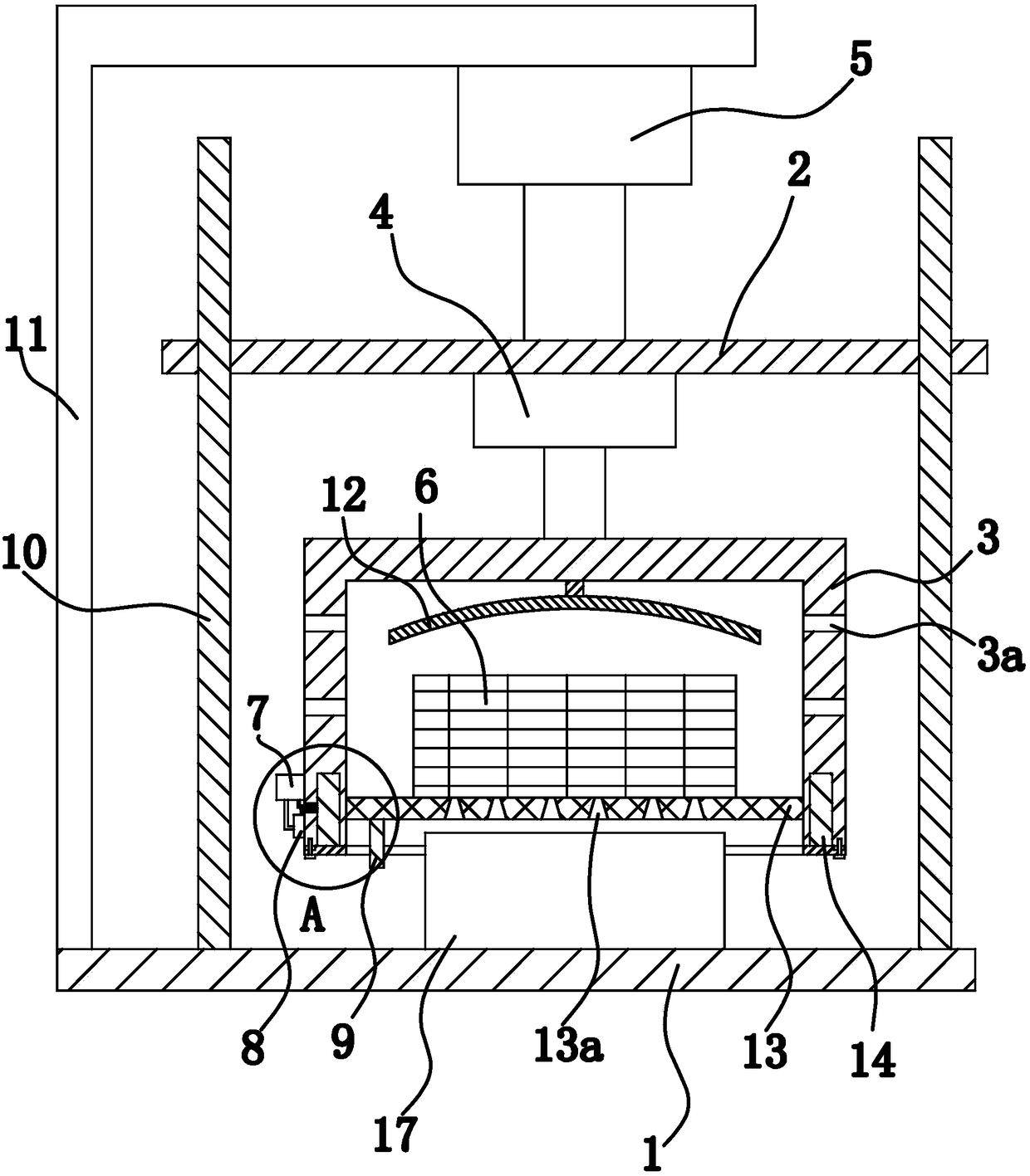
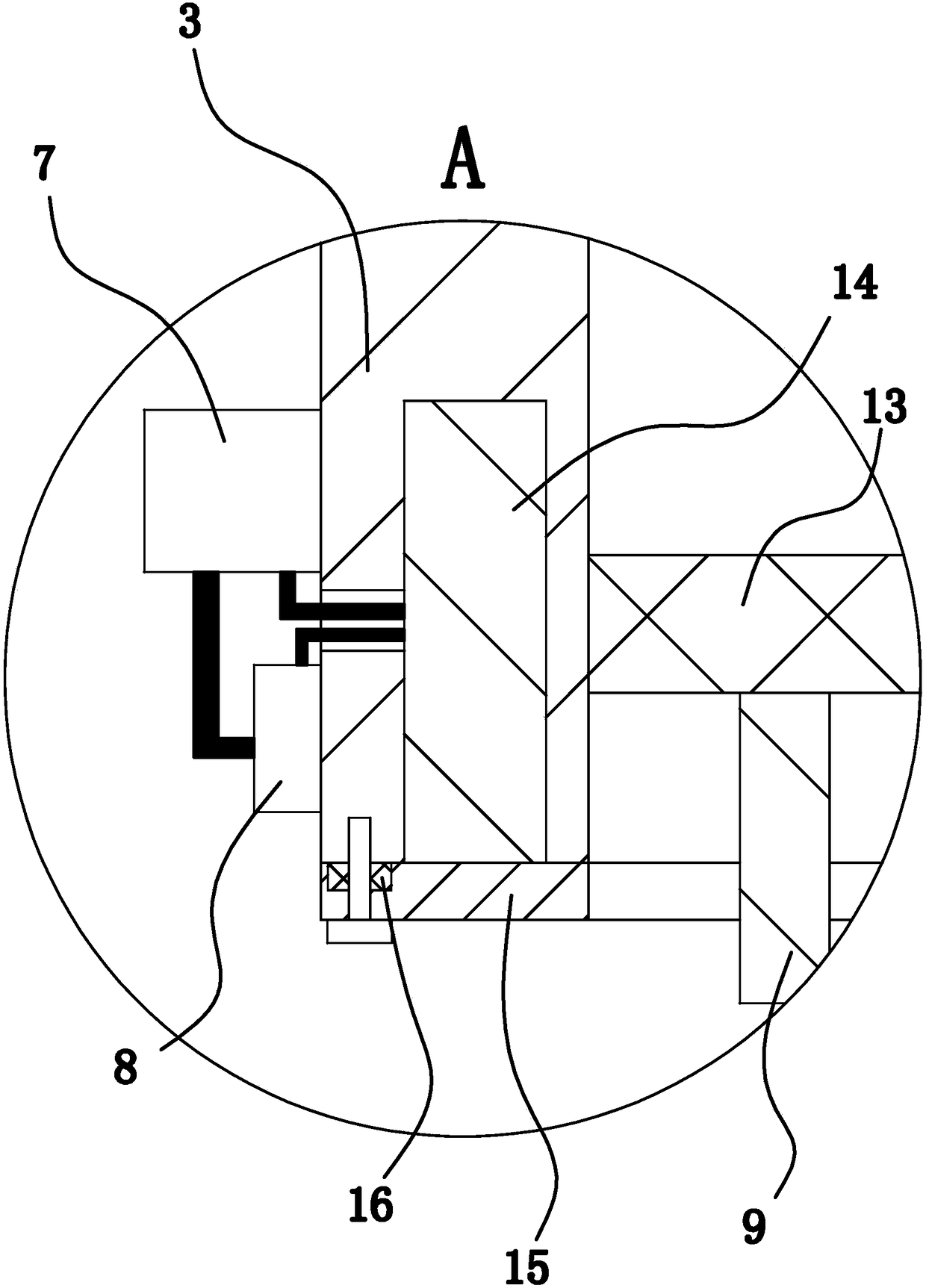
[0027] Such as figure 1 As shown, the medicinal material drying device in this pharmaceutical process consists of a workbench 1, a connecting plate 2, a drum 3, a motor 4, a cylinder 5, a grid box 6, a support plate 13, a battery 7, a switch 8, a pull rod 9, and a bracket 11, baffle plate 12, warm air blower 17 etc. are formed. Wherein, both the support plate 13 and the rotating drum 3 are made of magnetically permeable materials, and the magnetically permeable materials can be stainless steel, iron and the like. In this embodiment, preferably, both the support plate 13 and the drum 3 are made of stainless steel.

[0028] Specifically, two guide rods 10 are vertically fixed on the workbench 1; the connecting plate 2 is horizontally arranged on the workbench 1, and the connecting plate 2 is vertically penetrated with two guide holes, and the two guide holes connect with the two guide holes. The guide rods 10 are facing one by one, and the two guide rods 10 pass through the tw...

Embodiment 2

[0036] The structure and principle of this second embodiment are basically the same as that of the first embodiment, except that the lower end of the drum 3 is covered with a sealing cylinder, and the sealing cylinder is fixed to the drum 3 through a threaded structure. There is a ring-shaped protruding sealing part on the inner side wall of the lower end of the sealing cylinder, and the sealing part closes the notch of the groove by the way that the upper end surface of the sealing part abuts against the lower end surface of the drum 3 .


PUM


Abstract

The invention provides a medicinal material drying device used in the medicine manufacturing process. The problem that medicinal materials are inconvenient to take through existing medicinal material drying devices is solved. The medicinal material drying device used in the medicine manufacturing process comprises a workbench and a connecting plate arranged on the workbench. A drum is arranged between the connecting plate and the workbench. A motor capable of driving the drum to rotate is arranged on the connecting plate. A mesh box and a circular-arc-shaped baffle are arranged in the drum. A support and a fan heater are further fixedly arranged on the workbench. A cylinder capable of driving the connecting plate to translate up and down is arranged on the support. An annular groove is formed in the lower end face of the drum. An electromagnet is inserted and fixed in the groove. A supporting plate is arranged transversely in the drum. The side wall of the periphery of the supporting plate is attached to the inner side wall of the drum. The mesh box is fixed to the upper side of the supporting plate. A plurality of air guide holes are formed in the supporting plate in the vertical direction in a penetrating mode. An air outlet of the fan heater is located in the drum and directly faces the mesh box. The medicinal material drying device used in the medicine manufacturing process has the advantage that the medicinal materials are convenient to take.

Description

technical field [0001] The invention relates to a drying device, in particular to a medicinal material drying device in the pharmaceutical process. Background technique [0002] Now the drying box generally realizes drying directly by injecting heating air into the drying box, and this drying box has the disadvantage of low efficiency. [0003] For the above problems, people have realized the shortcomings and made improvements, such as a pharmaceutical fast hot air drying box for medicinal materials disclosed in the Chinese patent library [application number: 201521013290. , the top of the box is equipped with a rotating motor, the end of the rotor of the rotating motor is coaxial with the center of the top plate of the box and is fixedly connected, the outer surface of the box is provided with a through hole, and the inner cavity of the box is The middle device has a support rod, and there are two support rods, and a medicinal basket is fastened between the two support rod...

Claims


Application Information

Patent Timeline
Patent Type & Authority Patents(China)
IPC IPC(8): F26B11/08F26B21/00F26B25/00
CPCF26B11/024F26B11/026F26B11/028F26B11/08F26B21/003F26B25/00F26B25/002F26B25/008
Inventor 范素琴
Owner 宁远舜德医药有限公司
Learn More