A Hopkinson strut damper

A technology of Hopkinson compression rods and dampers, which is applied in the direction of instruments, shock absorbers, shock absorbers, etc., can solve the problems of surface wear of transmission rods, difficulty in placing test pieces, and affecting performance, etc., to achieve long service life, Small compressive deformation and good compressive performance

Inactive Publication Date: 2018-05-25
HEFEI UNIV OF TECH
View PDF14 Cites 0 Cited by
  • Summary
  • Abstract
  • Description
  • Claims
  • Application Information

AI Technical Summary

Problems solved by technology

When the length of the incident rod, the transmission rod or the length of the test specimen is too long, it will make it difficult or even impossible to place the specimen; when the length of the incident rod, the transmission rod or the length of the test specimen is too short, it will cause the If the distance between the dampers is too long, the sliding distance of the transmission rod is too long during the impact and reset process, which will cause greater wear on the surface of the transmission rod and affect its performance; In the middle, it is easy to cause plastic deformation such as thickening and bending of the transmission rod; when the metal end face of the damper is too small, it is easy to punch the transmission rod out of gaps or pits during the impact process

Method used


Image

  • A Hopkinson strut damper
  • A Hopkinson strut damper
  • A Hopkinson strut damper

Examples


Embodiment Construction

[0041] The embodiments of the present invention are described in detail below. This embodiment is implemented on the premise of the technical solution of the present invention, and detailed implementation methods and specific operating procedures are provided, but the protection scope of the present invention is not limited to the following implementation example.

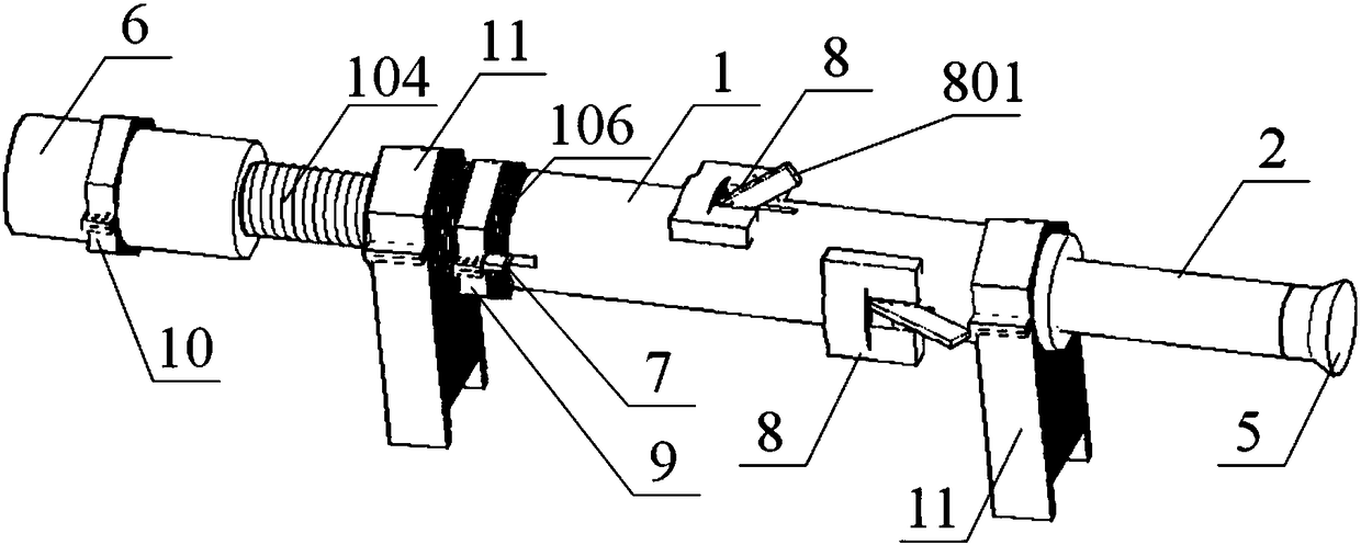
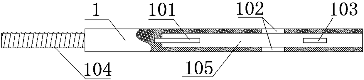
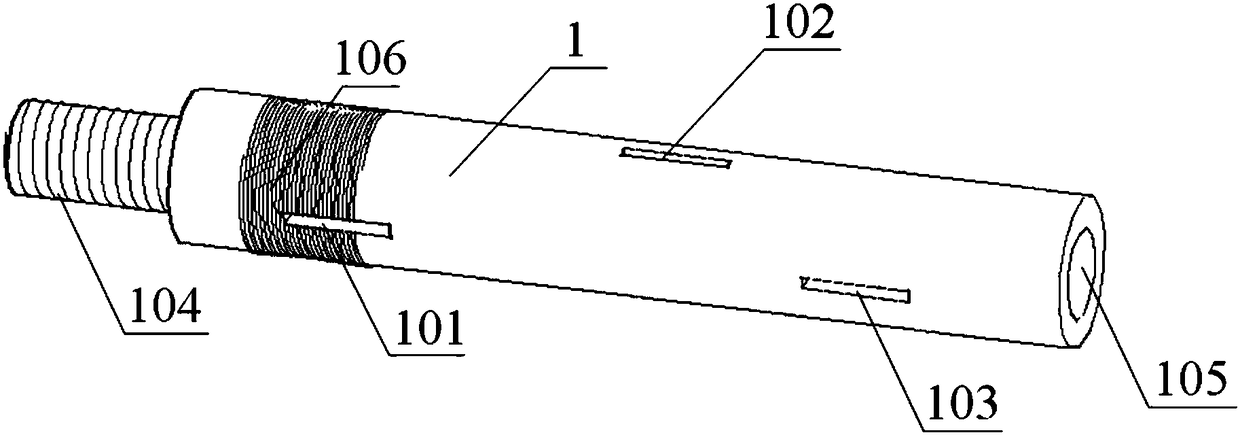
[0042] This embodiment discloses a Hopkinson compression bar damper, which includes a damping cylinder 1 and a damping rod 2. The center of the damping cylinder 1 is provided with a cavity 105 with an open end, and the end of the damping cylinder 1 is provided with a section The threaded shaft 104, the threaded shaft 104 is externally threaded with a damping sleeve 6, the damping sleeve 6 is fixed with a jacket 10, and the outer contour of the jacket 10 is a regular hexagon.

[0043] The inner end of the damping rod 2 is inserted into the cavity 105, and the outer end is provided with a buffer sleeve 5, and the cav...


PUM


Abstract

The invention discloses a Hopkinson pressure bar damper which comprises a damping cylinder and a damping rod. The center of the damping cylinder is provided with a cavity of which one end is open, the inner end of the damping rod is inserted into the cavity, the cavity is further provided with a pushing plate and a damping spring, and the damping spring is located between the pushing plate and the inner end of the damping rod; an annular limiting groove is formed in the portion, close to the inner end, of the damping rod, the damping cylinder is provided with two sets of spring lock mechanisms at different positions in the axis direction of the damping cylinder, and when the damping rod moves to the annular limiting groove of the damping rod to correspond to the front ends of locking sections of the spring lock mechanisms, the damping rod can be locked. Compared with the prior art, the Hopkinson pressure bar damper has the following advantages of being good in compression resistance, small in compressive deformation, high in energy absorption efficiency, long in service life, high in independence of all the parts and suitable for Hopkinson pressure bar experiments at the different elastic speeds, different rod qualities, different rod lengths, different rod diameters and different test sample lengths.

Description

technical field [0001] The invention relates to the technical field of testing equipment for dynamic mechanical properties of materials, in particular to a Hopkinson compression bar damper. Background technique [0002] The Hopkinson compression bar test method is the most important and reliable experimental method for studying the mechanical properties of materials at medium and high projectile velocities, and is an important part of the experimental technology of explosion and impact dynamics. The use of Hopkinson rods can not only achieve uniaxial tension, compression, and shear loading at high elastic velocities, but also develop dynamic compression-shear composite loading, active and passive confining pressure and other complex loading, as well as medium elastic velocity loading. Both the development of science and the practical application of engineering play a very important role. [0003] The separated Hopkinson compression rod test system is usually composed of an ...

Claims


Application Information

Patent Timeline
Patent Type & Authority Patents(China)
IPC IPC(8): G01N3/02F16F13/00
CPCF16F13/005G01N3/02
Inventor 王志亮毕程程
Owner HEFEI UNIV OF TECH
Why Eureka
Try Eureka