
Fluorescence Intensity Measurement Method for Automatic Magnetic Particle Inspection

A technology of fluorescence intensity and magnetic particle flaw detection, which is applied in the field of fluorescence intensity measurement, can solve the problems of lack of online detection of fluorescence intensity, and achieve the effect of avoiding human error and accurate fluorescence intensity

Active Publication Date: 2019-03-05
BAOSHAN IRON & STEEL CO LTD
View PDF4 Cites 0 Cited by
  • Summary
  • Abstract
  • Description
  • Claims
  • Application Information

AI Technical Summary

Problems solved by technology

[0006] In view of the lack of means for online detection of fluorescence intensity in the prior art and mainly relying on manual experience to judge the problem, the purpose of the present invention is to provide a method for measuring fluorescence intensity for automatic magnetic particle flaw detection

Method used


Image

  • Fluorescence Intensity Measurement Method for Automatic Magnetic Particle Inspection
  • Fluorescence Intensity Measurement Method for Automatic Magnetic Particle Inspection
  • Fluorescence Intensity Measurement Method for Automatic Magnetic Particle Inspection

Examples


Embodiment Construction

[0023] The technical solutions of the present invention will be further described below in conjunction with the accompanying drawings and embodiments.

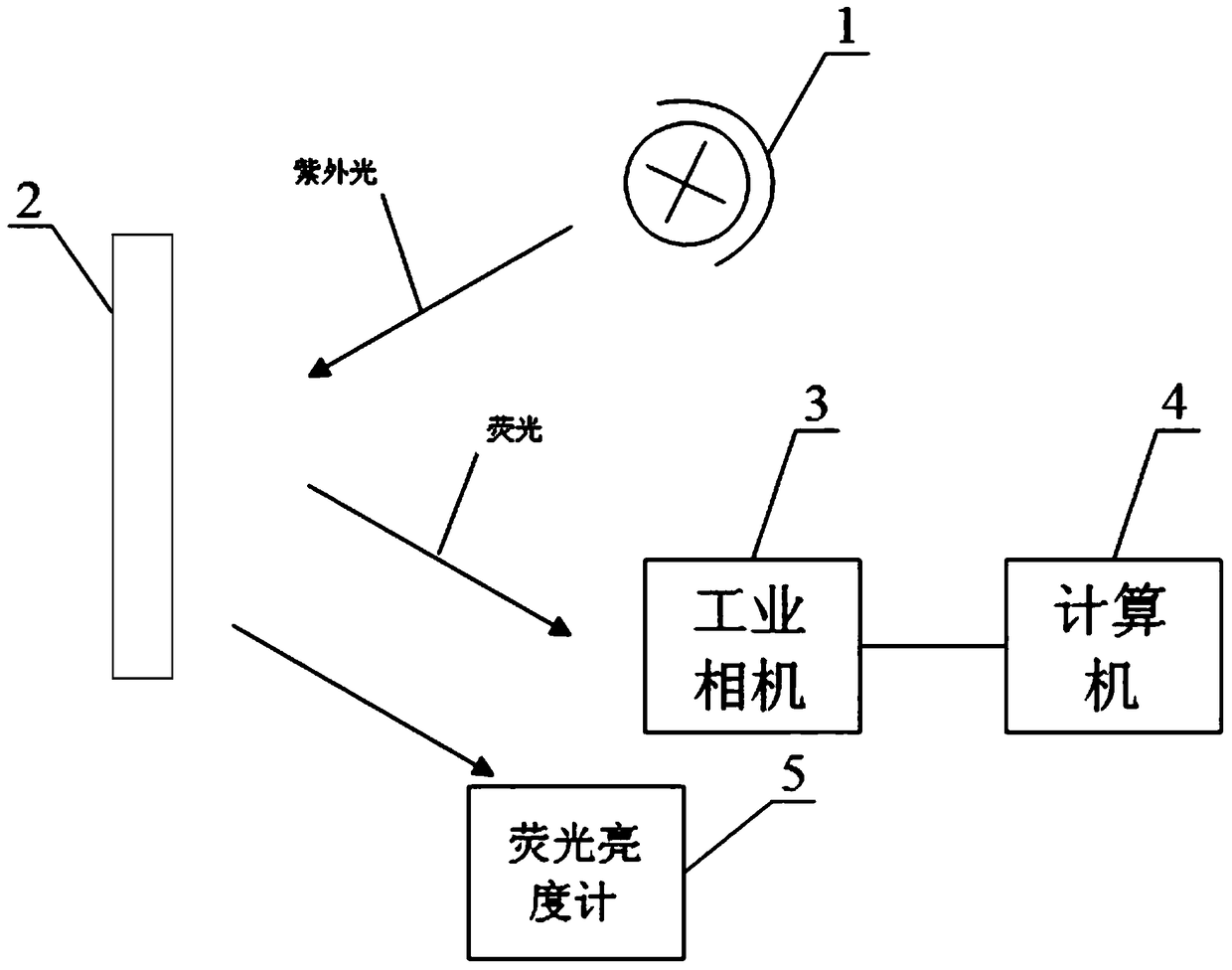
[0024] refer to figure 1 , the present invention first discloses a fluorescence intensity measuring device for automatic magnetic particle flaw detection, which mainly includes an ultraviolet light source 1, an imaging device 3, a computer 4, a fluorescence luminance meter 5, and a sensitivity test piece (not shown in the figure). In the imaging device 3 of the present invention, the imaging device is an industrial CCD camera, but it is not limited thereto.

[0025] Such as figure 1 As shown, when the ultraviolet light source 1 irradiates the workpiece 2 to be measured, the imaging device 3 takes a fluorescent image of the workpiece 2 to be measured, and transmits the fluorescent image to the computer 4 . The sensitivity test piece is placed on the workpiece 2 to be tested and includes a cross mark, and the fluorescence lumi...


PUM


Abstract

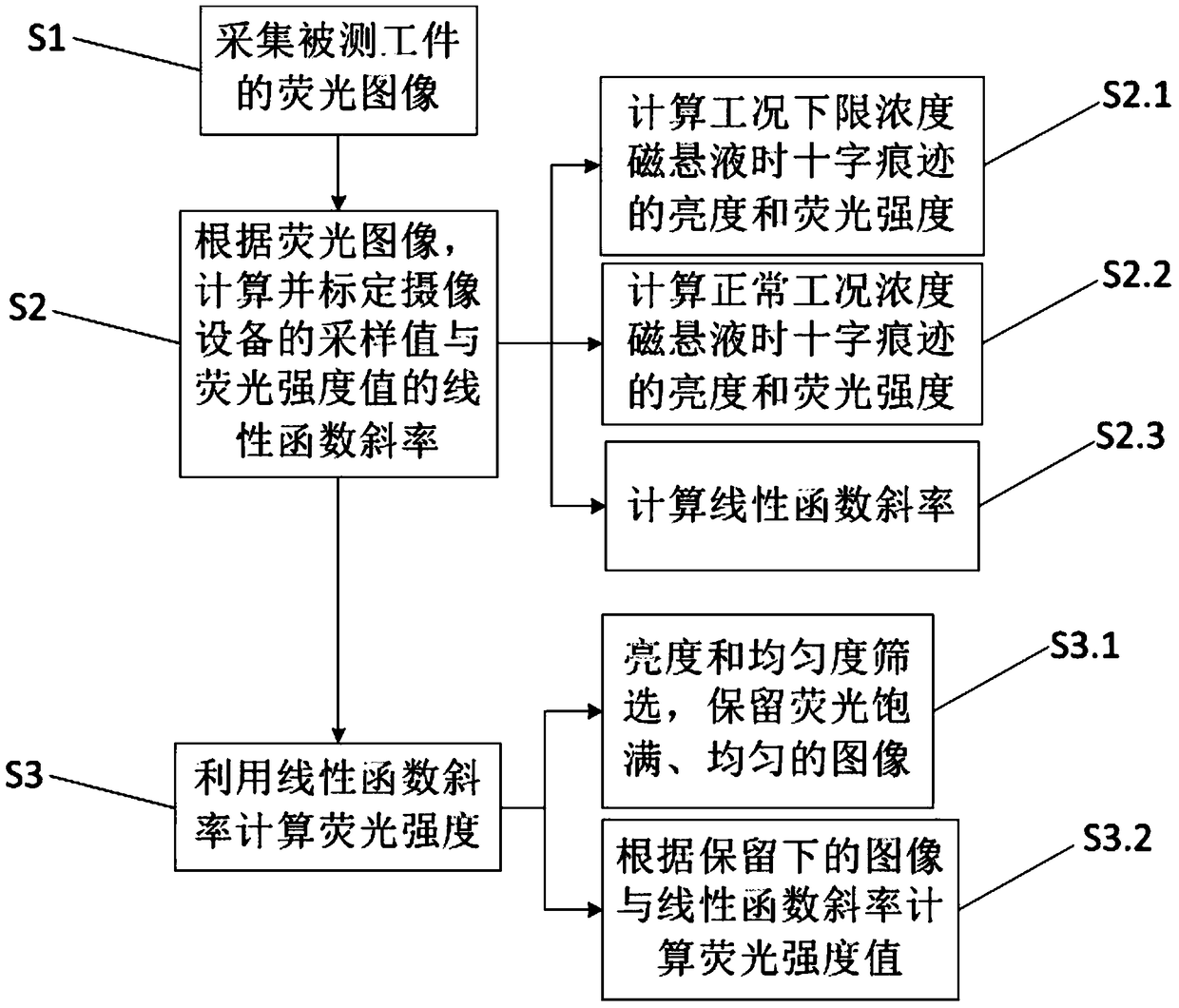
The invention discloses a method for measuring fluorescence intensity used for automatic magnetic powder inspection and an apparatus thereof. The apparatus comprises uv light source, a camera device, a computer, a fluorescence luminance meter, and a sensitivity test piece. The uv light source irradiates a workpiece to be measured, the camera device takes fluoroscopic images of the workpiece, and then the fluoroscopic image is transmitted to the computer. The sensitivity test piece is placed on the workpiece, and comprises a cross mark, and the fluorescence luminance meter detects the fluorescence intensity of the cross mark. The method comprises the following steps: 1) collecting the fluoroscopic images of the workpiece to be measured; 2) according to the fluoroscopic images, calculating and calibrating a linear function gradient of a sampling value and a fluorescence intensity value; and 3) using the linear function gradient to calculate the fluorescence intensity. The method can automatically calculate the defect fluoroscopic images of the workpiece, accurate fluorescence intensity can be obtained, and personal error can be avoided.

Description

technical field [0001] The invention relates to a method for measuring fluorescence intensity, more particularly, to a method for measuring fluorescence intensity for automatic magnetic particle flaw detection. Background technique [0002] Magnetic particle flaw detection uses the interaction between the leakage magnetic field at the defect of the workpiece and the magnetic powder. It uses the difference between the magnetic permeability of the surface of the steel product and the near-surface defects (such as cracks, slag inclusions, hairlines, etc.) and the magnetic permeability of the steel. After magnetization, these The magnetic field at the discontinuity of the material will change, forming a part of the magnetic flux leakage, and a leakage magnetic field will be generated on the surface of the workpiece, thereby attracting magnetic powder to form a magnetic particle accumulation at the defect - a magnetic mark. Under appropriate lighting conditions, the defect positio...

Claims


Application Information

Patent Timeline
Patent Type & Authority Patents(China)
IPC IPC(8): G01N21/64G01N21/88G01J1/58
Inventor 胡继康申屠理锋邹堃陈林李劲刘祖表奚嘉奇
Owner BAOSHAN IRON & STEEL CO LTD
Learn More