


Quick Research
Generate reliable direction feasibility study reports for your R&D in just a few steps.

Technical Q&A
Discover and master advanced knowledge NOW. Basics, ideas, possibilities, all at once.

Find Solutions
As an expert in R&D theories, this can generate solutions to your technical problems instantly.

Evaluate Feasibility
Analyze your overall solution with one click, know your potential R&D risks in advance.

Monitor Landscape
Get weekly tech updates, stay abreast of the latest tech innovations and key insights.
Survey data processing device, survey data processing method, and program therefor
一种处理装置、测量数据的技术,应用在图像数据处理、涉及图形用户界面的详细信息、图像分析等方向,能够解决非效率、错误检测、繁杂等问题,达到提高效率的效果
- Summary
- Abstract
- Description
- Claims
- Application Information
AI Technical Summary
Problems solved by technology
Method used
Image

Examples
no. 1 approach
[0037] (summary)
[0038] Hereinafter, the principle of processing performed in the embodiment will be briefly described. exist figure 1 The principle of the measurement is shown conceptually in . In this example, an unmanned aircraft (UAV (Unmanned Air Vehicle)) 10 capable of flying autonomously is mounted with a camera capable of taking pictures. The UAV 10 is equipped with a GNSS device (a position specifying device using navigation satellites) and an IMU (inertial navigation unit) and is capable of autonomous flight, but its accuracy is insufficient for creating a three-dimensional model described later. Of course, although the cost increases, a UAV equipped with a high-precision GNSS device and an IMU can also be used. In addition, in the creation of the three-dimensional model in this embodiment, the GNSS device and the IMU of the UAV are not essential. Furthermore, it is also possible to use aircraft that are not UAVs but manned.
[0039] UAV10 continuously takes p...
no. 2 approach
[0150] In the present invention, three-dimensional point cloud position data (or a three-dimensional model based on the three-dimensional point cloud position data) obtained by a total station with a camera and a laser scanner can also be used together. In this case, the first three-dimensional model is created by the method described in the first embodiment without using reference points. The three-dimensional model (No. 1) is a relative model in which the relative positional relationship between feature points is specified, since the designation of the reference point as in the first embodiment is not performed.
[0151] On the other hand, in addition to a laser distance measuring device, a total station equipped with a camera (for example, refer to Japanese Patent Application Laid-Open No. 2014-173990 ) and a laser scanner are used to point the area overlapping with the three-dimensional model (Part 1). The group position data is obtained, and a three-dimensional model base...
no. 3 approach
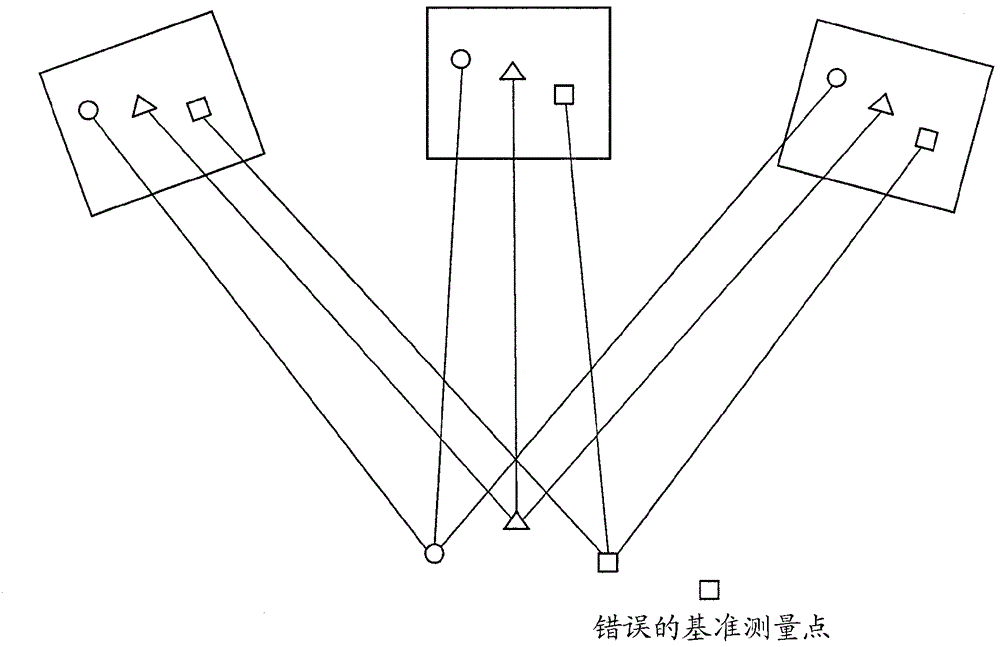
[0155] In the first embodiment, it is also possible to automatically detect the reference point specified initially by image recognition. In this case, a plurality of positions (four or more positions) commonly appearing in the first two still images selected are thoroughly clarified to set a reference target for easy image recognition. Regarding this reference target, in order to facilitate image recognition, the installation location is determined while paying attention to the state of the ground surface serving as the background. In addition, objects other than the reference object are arranged in the same manner as in the case of the first embodiment.
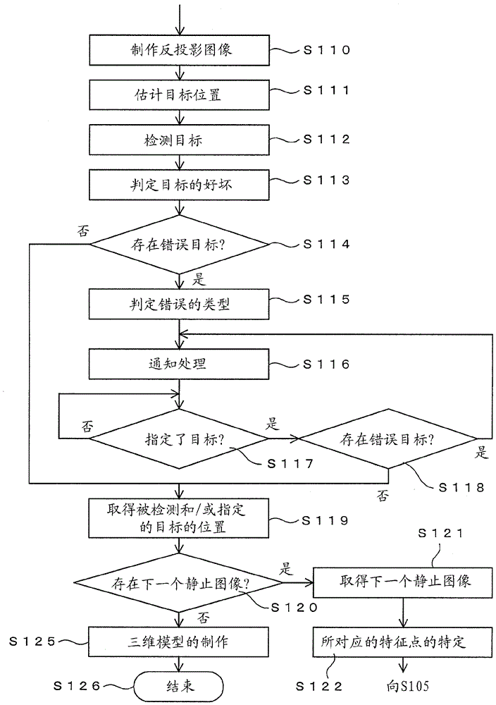
[0156]In the case of this example, detection of a target is performed by software processing from the still image selected in step S102. Thereafter, the same processing as in the first embodiment is performed. In the present embodiment, it is necessary to set the first detected object as a special object that is easy to a...
PUM
 Abstract
Description
Claims
Application Information
 - R&D Engineer
- R&D Manager
- IP Professional
- Industry Leading Data Capabilities
- Powerful AI technology
- Patent DNA Extraction
Browse by: Latest US Patents, China's latest patents, Technical Efficacy Thesaurus, Application Domain, Technology Topic, Popular Technical Reports.
© 2024 PatSnap. All rights reserved.Legal|Privacy policy|Modern Slavery Act Transparency Statement|Sitemap|About US| Contact US: help@patsnap.com