

Smart Controller Panel Unit
An intelligent controller and panel technology, applied in emergency protection devices, parts of protection switches, electrical components, etc., can solve problems such as easy entry of moisture and dust, and achieve the effect of improving adjustment speed and safety performance.
- Summary
- Abstract
- Description
- Claims
- Application Information
AI Technical Summary
Problems solved by technology
Method used
Image

Examples
Embodiment 1
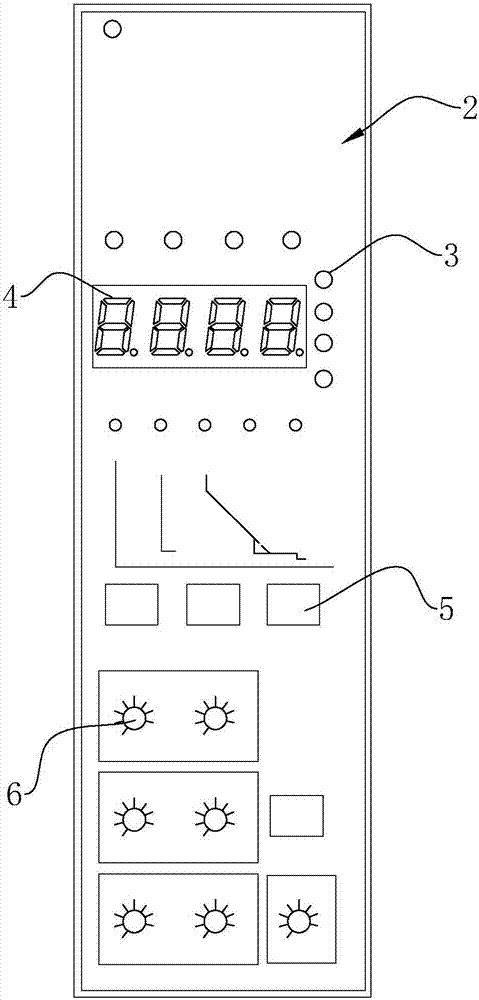
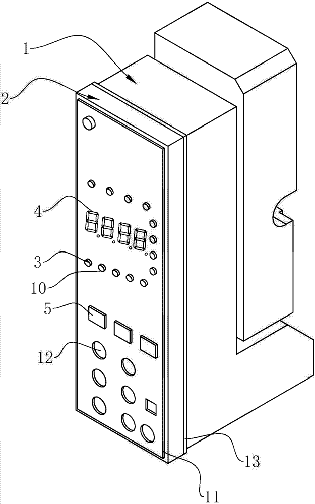
[0037] like figure 1 As shown in -5, an intelligent control panel 2 device includes a base 1 and a panel 2 engaged with the base 1. The base 1 is mainly the housing of a molded case circuit breaker, see figure 1 , 2 , the panel 2 is provided with a status indicator light 3, a digital tube 4, a button 5 and a knob 6, and the panel 2 is provided with a through hole 10 for the status indicator light 3, a digital tube 4, a button 5 and a knob 6. The main material is plastic. The panel 2 is covered with a layer of flexible film 11. The flexible film 11 is crystal epoxy or POPP film. The flexible film 11 is provided with a mounting hole 12 for the knob 6 to pass through. The mounting hole 12 is circular. The panel 2 is provided with a humidity sensing control circuit B for detecting the humidity of the external environment and adjusting the temperature of the panel 2 according to the ambient humidity.
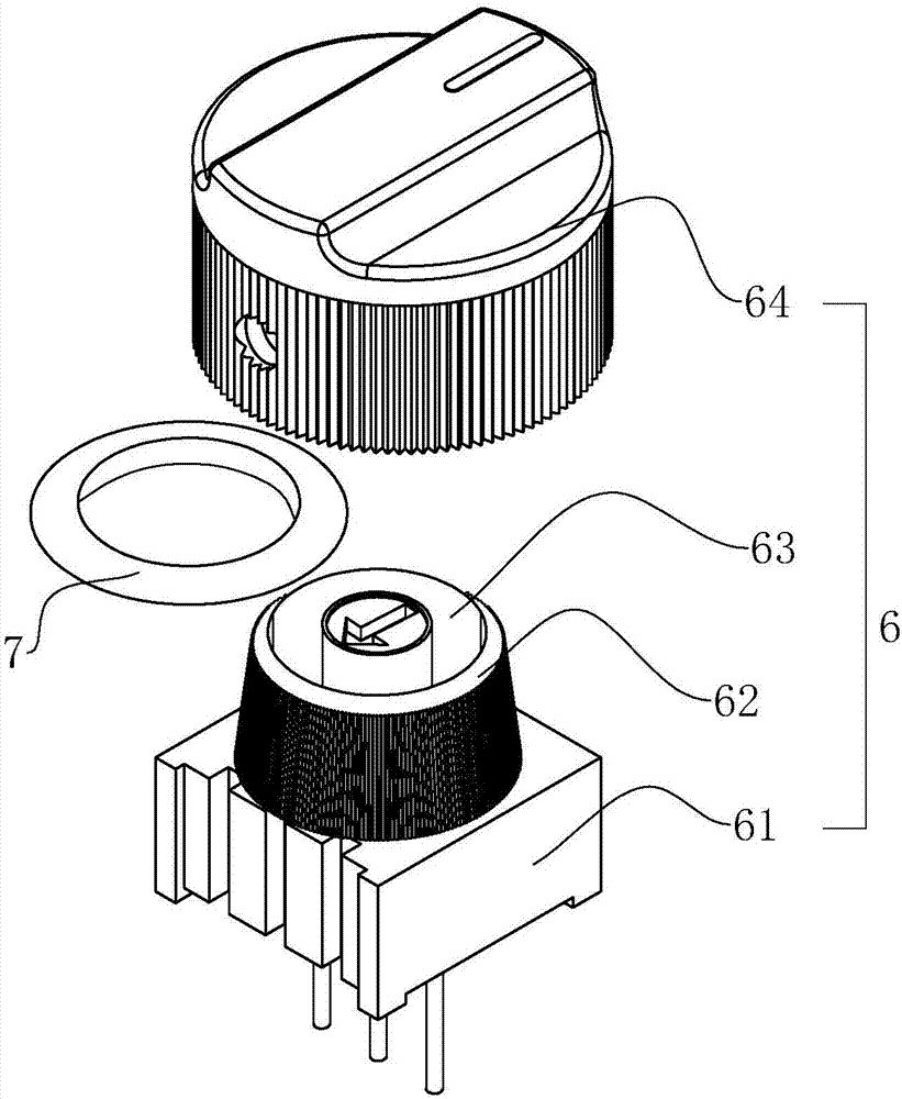
[0038] like image 3-5, for its mechanical structure: the knob 6 includes a ...
Embodiment 2
[0047] The difference from Embodiment 1 is that the comparison unit B3 may also include a first comparison circuit B31 for setting the normal limit threshold and outputting a first level signal for indication. For the first comparison circuit B31, refer to Figure 7 , including the comparator U1, the supply circuit of the reference signal Vref1, the LED2 used to indicate the state and the current limiting resistor R16, wherein the supply circuit of the reference signal Vref1 is: one end of the resistor R11 is connected to the power supply Vcc, and the other end of the resistor R11 is connected in series with the potentiometer W2 The resistor R10 is connected in series to the ground, and the adjustment terminal of the potentiometer W2 is connected to the inverting terminal of the comparator U2. The potentiometer W2 can adjust the size of the normal threshold.
[0048] The analog signal S1 is input to the non-inverting terminal of the comparator U1, and is output after being comp...
Embodiment 3
[0050] The difference from Embodiment 2 is that the comparison unit B3 may also include a third comparison circuit B33 for setting an alarm threshold and outputting a third level signal for indication, including a comparator U3, a supply circuit for a reference signal Vref3, and a circuit for The LED3 indicating the state and the current limiting resistor R17, wherein the supply circuit of the reference signal Vref3 is: one end of the resistor R14 is connected to the power supply Vcc, the other end of the resistor R14 is connected in series with the potentiometer W3, and then the resistor R13 is connected in series with the ground, and the adjusting end of the potentiometer W3 is connected to the comparator The inverting terminal of U3, the potentiometer W3 can adjust the size of the alarm threshold.
[0051] The analog signal S1 is input to the non-inverting terminal of the comparator U3, and is output after being compared with the reference signal Vref3. When the humidity is ...
PUM
 Abstract
Description
Claims
Application Information