Mobile terminal and focusing method
A mobile terminal and object technology, applied in the field of photography, can solve the problems of not realizing the automatic focus function of the front camera, the indistinct degree of picture details, and the lack of layering in the scene, so as to improve the experience, focus quickly, and have a strong sense of layering Effect
- Summary
- Abstract
- Description
- Claims
- Application Information
AI Technical Summary
Problems solved by technology
Method used
Image
Examples
Embodiment 1
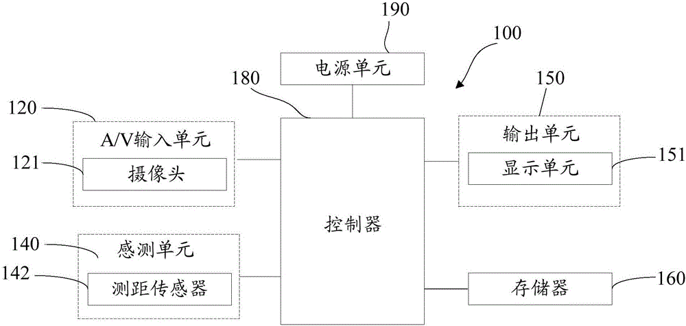
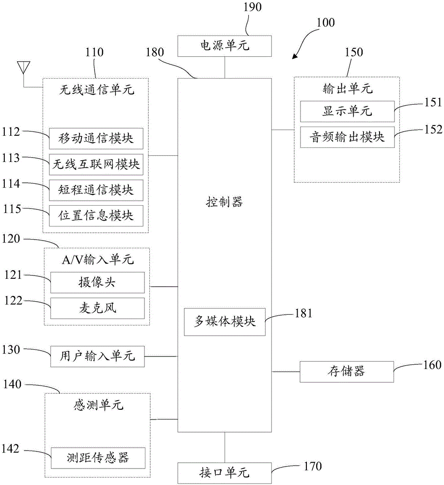
[0081] The mobile terminal 100 described in this embodiment adopts figure 1 The hardware structure shown is, of course, in the figure 1 On the basis of the actual implementation, it can be implemented in the mobile terminal 100 as needed figure 2 Some or all of the functional modules shown in .
[0082] Such as figure 1 As shown, the mobile terminal 100 described in this embodiment is provided with a camera 121. Generally, the camera 121 is arranged on the back panel of the mobile terminal 100 to become the rear camera 121. In order to meet the needs of business scenarios such as video calls, the camera 121 can be It is set on at least one of the front panel and rear panel of the mobile terminal 100; of course, the mobile terminal 100 may also only set the camera 121 on the front panel.
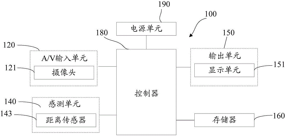
[0083] Such as Figure 3-1 as shown, figure 1 The shown distance sensor 142 is implemented as a distance sensor 143 in this embodiment, for example, it can be an infrared distance senso...
Embodiment 2
[0103] The mobile terminal 100 described in this embodiment adopts figure 1 The hardware structure shown is, of course, in the figure 1 On the basis of the actual implementation, it can be implemented in the mobile terminal 100 as needed figure 2 Some or all of the functional modules shown in .
[0104] Such as Figure 3-2 As shown, the mobile terminal 100 described in this embodiment is provided with a camera 121. Generally, the camera 121 is arranged on the back panel of the mobile terminal 100 to become the rear camera 121. In order to meet the needs of business scenarios such as video calls, the camera 121 can be It is set on at least one of the front panel and rear panel of the mobile terminal 100; of course, the mobile terminal 100 may also only set the camera 121 on the front panel.
[0105] Such as Figure 5 as shown, figure 1 The shown ranging sensor 142 is implemented as a binocular camera 143 in this embodiment, and the binocular camera 143 includes two lens m...
Embodiment 3
[0113] Corresponding to the focusing processing of the mobile terminal 100 described in the foregoing embodiments, this embodiment provides a focusing method applied to a mobile terminal, see Figure 7 , including the following steps:
[0114] Step 101, sensing objects in the environment to obtain sensing data characterizing the position of the objects in the environment.
[0115] Step 102, based on the sensing data, determine the object distance parameter formed by the object relative to the camera 121, and determine the image distance parameter used by the camera 121 based on the object distance parameter;
[0116] The image distance parameter is determined based on the following correspondence between the object distance parameter, the focal length parameter of the camera 121 , and the image distance parameter: the sum of the reciprocal of the object distance parameter and the reciprocal of the image distance parameter is equal to the reciprocal of the focal length paramete...
PUM
 Abstract
Description
Claims
Application Information
 - R&D
- Intellectual Property
- Life Sciences
- Materials
- Tech Scout
- Unparalleled Data Quality
- Higher Quality Content
- 60% Fewer Hallucinations
Browse by: Latest US Patents, China's latest patents, Technical Efficacy Thesaurus, Application Domain, Technology Topic, Popular Technical Reports.
© 2025 PatSnap. All rights reserved.Legal|Privacy policy|Modern Slavery Act Transparency Statement|Sitemap|About US| Contact US: help@patsnap.com


